SECTION 1: SPECIFICATION INFORMATION
TYPICAL ELECTRIC AND GAS BOOSTER DIMENSIONS
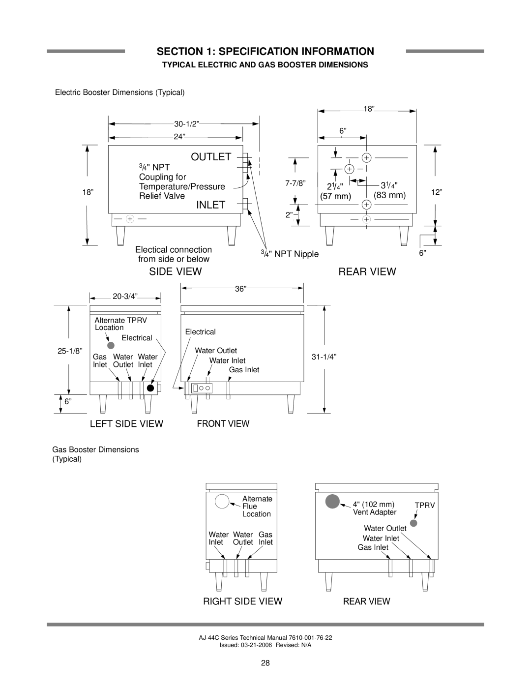
Electric Booster Dimensions (Typical)
|
|
|
|
|
|
|
|
|
|
|
|
|
| OUTLET |
|
|
|
|
|
|
|
|
|
|
|
|
|
|
|
|
|
|
|
|
|
|
| ||
|
|
|
|
|
|
|
|
|
|
|
|
|
|
|
|
| |||
|
|
|
|
|
|
|
|
|
|
|
|
|
|
|
|
|
| ||
|
|
|
|
|
|
|
|
|
|
|
|
| 3/4" NPT |
|
|
| |||
|
|
|
|
|
|
|
|
|
|
|
|
| Coupling for |
|
|
| |||
|
|
|
|
|
|
|
|
|
|
|
|
|
|
|
| ||||
|
|
|
|
|
|
|
|
|
|
|
|
|
|
|
| ||||
18” |
|
|
|
|
|
|
|
|
|
|
| Temperature/Pressure |
|
|
| ||||
|
|
|
|
|
|
|
|
|
|
| Relief Valve |
|
|
| |||||
|
|
|
|
|
|
|
|
|
|
|
|
|
|
|
| ||||
|
|
|
|
|
|
|
|
|
|
|
|
|
| INLET |
|
|
|
| |
|
|
|
|
|
|
|
|
|
|
|
|
|
|
|
|
|
| ||
|
|
|
|
|
|
|
|
|
|
|
|
|
|
|
|
|
|
| |
|
|
|
|
|
|
|
|
|
|
|
|
|
|
|
|
|
|
|
|
|
|
|
|
|
|
|
|
|
|
|
|
|
|
|
|
|
|
|
|
|
|
|
|
|
|
|
|
|
|
|
|
|
|
|
|
|
|
|
|
|
|
|
|
|
|
|
|
|
|
|
|
|
|
|
|
|
|
|
|
Electical connection from side or below
SIDE VIEW
18”
18" (457 mm) 6"
(1526”mm)
77/8" | 11 |
|
| ||
(200 mm) 21/4 | 33//4" | 12” |
| (83 mm) | |
2” |
|
|
3 |
| 6” |
/4" NPT Nipple | 6" (152 mm) | |
REAR VIEW
 36" (914 mm)36”
 PMG-200 
![]()
![]() 20-3/4”
20-3/4”![]()
![]()
![]()
![]()
![]()
Alternate TPRV
LocationElectrical
Electrical
Gas | Water | Water | Water Outlet | ||
| Water Inlet | ||||
| Inlet | Outlet | Inlet |
| |
| Gas Inlet |
| |||
|
|
|
|
|
![]()
![]()
![]() 6”
6”![]()
![]()
LEFT SIDE VIEW
Gas Booster Dimensions |
|
|
|
|
(Typical) |
|
| 36" (914 mm) | |
|
|
| ||
| Alternate | 4" (102 mm) | TPRV | |
| Flue |
| ||
| Location | Vent Adapter |
| |
Water | Water | Gas | Water Outlet |
|
Water Inlet |
| |||
Inlet | Outlet | Inlet |
| |
Gas Inlet |
| |||
|
|
|
| |
RIGHT SIDE VIEW
Issued:
28