Page 14
Operation
3Operation
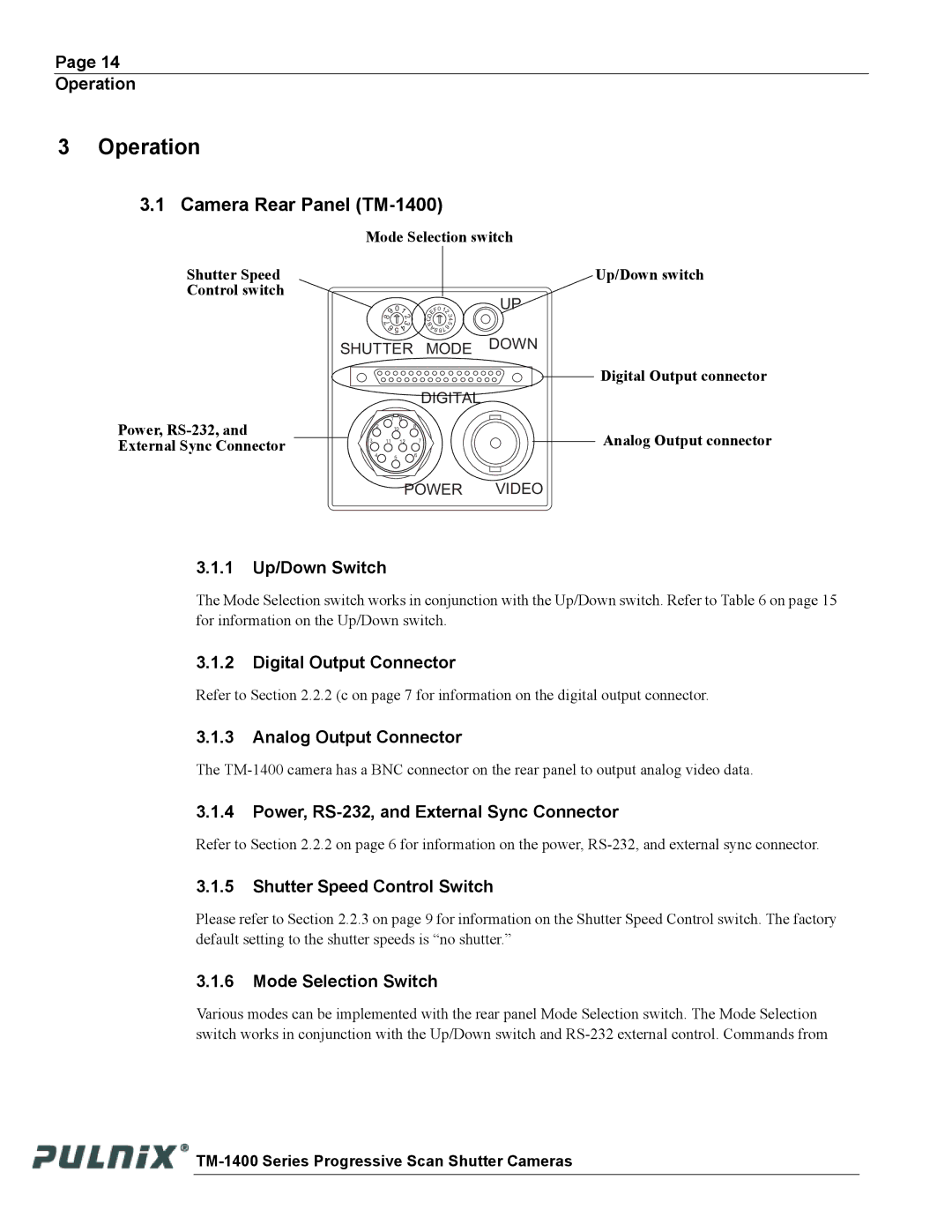
3.1Camera Rear Panel (TM-1400)
Mode Selection switch
Shutter Speed
Control switch
8 | 9 | 01 | |
| 2 | ||
|
| 3 | |
7 |
| ||
| 6 | ||
| 4 | ||
|
| 5 |
|
Up/Down switch
F0 | 12 |
| |
E |
| 3 | |
D |
|
| 4 |
C |
|
| |
B |
| 6 | 5 |
A |
|
| |
9 |
| 7 |
|
8 |
| ||
SHUTTER MODE DOWN
Digital Output connector
DIGITAL
Power,
1 9
28
10
3 11 12 7
4 5 6
![]() Analog Output connector
Analog Output connector
POWER VIDEO
3.1.1Up/Down Switch
The Mode Selection switch works in conjunction with the Up/Down switch. Refer to Table 6 on page 15 for information on the Up/Down switch.
3.1.2Digital Output Connector
Refer to Section 2.2.2 (c on page 7 for information on the digital output connector.
3.1.3Analog Output Connector
The
3.1.4Power,
Refer to Section 2.2.2 on page 6 for information on the power,
3.1.5Shutter Speed Control Switch
Please refer to Section 2.2.3 on page 9 for information on the Shutter Speed Control switch. The factory default setting to the shutter speeds is “no shutter.”
3.1.6Mode Selection Switch
Various modes can be implemented with the rear panel Mode Selection switch. The Mode Selection switch works in conjunction with the Up/Down switch and
![]()