Page 15
Operation
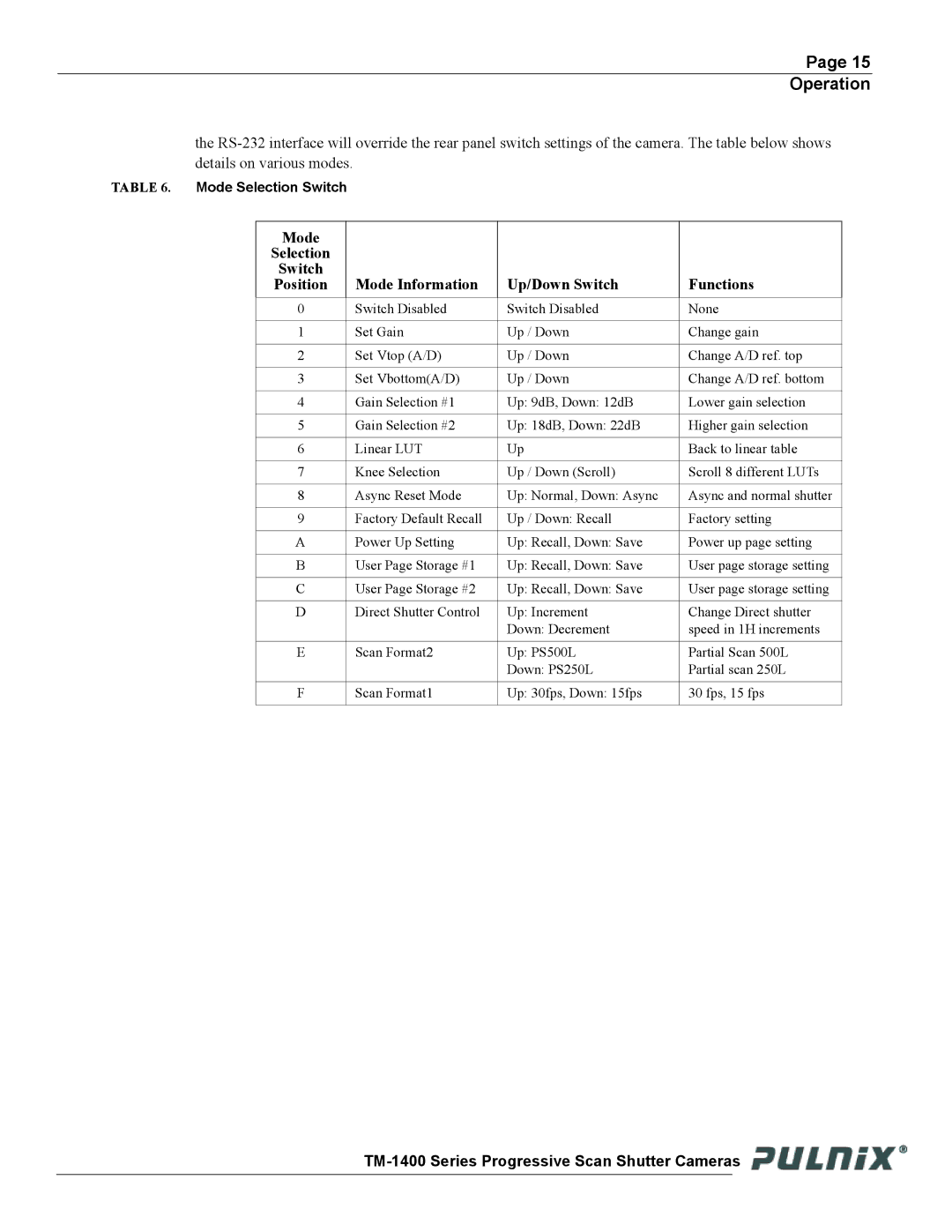
the
TABLE 6. Mode Selection Switch
Mode
Selection
Switch
Position
Mode Information
Up/Down Switch
Functions
0 | Switch Disabled | Switch Disabled | None |
|
|
|
|
1 | Set Gain | Up / Down | Change gain |
|
|
|
|
2 | Set Vtop (A/D) | Up / Down | Change A/D ref. top |
|
|
|
|
3 | Set Vbottom(A/D) | Up / Down | Change A/D ref. bottom |
|
|
|
|
4 | Gain Selection #1 | Up: 9dB, Down: 12dB | Lower gain selection |
|
|
|
|
5 | Gain Selection #2 | Up: 18dB, Down: 22dB | Higher gain selection |
|
|
|
|
6 | Linear LUT | Up | Back to linear table |
|
|
|
|
7 | Knee Selection | Up / Down (Scroll) | Scroll 8 different LUTs |
|
|
|
|
8 | Async Reset Mode | Up: Normal, Down: Async | Async and normal shutter |
|
|
|
|
9 | Factory Default Recall | Up / Down: Recall | Factory setting |
|
|
|
|
A | Power Up Setting | Up: Recall, Down: Save | Power up page setting |
|
|
|
|
B | User Page Storage #1 | Up: Recall, Down: Save | User page storage setting |
|
|
|
|
C | User Page Storage #2 | Up: Recall, Down: Save | User page storage setting |
|
|
|
|
D | Direct Shutter Control | Up: Increment | Change Direct shutter |
|
| Down: Decrement | speed in 1H increments |
|
|
|
|
E | Scan Format2 | Up: PS500L | Partial Scan 500L |
|
| Down: PS250L | Partial scan 250L |
|
|
|
|
F | Scan Format1 | Up: 30fps, Down: 15fps | 30 fps, 15 fps |
|
|
|
|
![]()
