438335-UIM-B-0509


Table 14: Free Area


Minimum Free Area Required for Each Opening


When a Category I furnace is removed or replaced, the original


BTUH Input


Horizontal Duct

Vertical Duct or

Round Duct

venting system may no longer be correctly sized to properly vent


Rating

Opening to Outside

the attached appliances.


(2,000 BTUH)

(4,000 BTUH)

An improperly sized vent system can cause CARBON MONOXIDE


(4,000 BTUH)


60,000

30 in2 (193 cm2)

15 in2 (97 cm2)

5” (13 cm)

to spill into the living space causing personal injury, and or death.

Table 13: Unconfined Space Minimum Area in Square Inch


80,000

40 in2 (258 cm2)

20 in2 (129 cm2)


5” (13 cm)


100,000

50 in2 (322 cm2)

25 in2 (161 cm2)


6” (15 cm)

BTUH Input Rating

Minimum Free Area in Square Inches

120,000

60 in2 (387 cm2)

30 in2 (193 cm2)


7” (18 cm)

Required for Each Opening


EXAMPLE: Determining Free Area.


60,000


60 (387 cm2)


Appliance 1 Appliance 2 Total Input


80,000


80 (516 cm2)


100,000 +30,000 = (130,000 ÷ 4,000) = 32.5 Sq. In. Vertical

100,000


100 (645 cm2)


Appliance 1 Appliance 2 Total Input


100,000 +30,000 = (130,000 ÷ 2,000) = 65 Sq. In. Horizontal

120,000


120 (742 cm2)


Gas


Gas


Gas


Vent


Gable


Gable


Vent


Vent


Vent


Vent


Ventilated


Ventilated


Attic


Optional


Attic


Top Above


Inlet (a)


Top Above


Insulation


Insulation


Soffit

Outlet


Vent

Air (a)


Soffit


Outlet


Outlet


Vent


Air (b)


Air (a)


Gas

Furnace


Water


Gas

Furnace


Gas

Furnace


Heater


Water


Water


Inlet

Heater


Inlet

Inlet

Heater

Inlet


Ventilated

Air (b)


Air (a)

Air (b)


Air (a)


Crawl Space


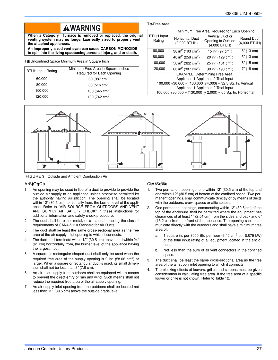
FIGURE 37: Outside and Ambient Combustion Air

Air Supply Openings and Ducts

1.An opening may be used in lieu of a duct to provide to provide the outside air supply to an appliance unless otherwise permitted by the authority having jurisdiction. The opening shall be located within 12” (30.5 cm) horizontally from, the burner level of the appli- ance. Refer to “AIR SOURCE FROM OUTDOORS AND VENT AND SUPPLY AIR SAFETY CHECK” in these instructions for additional information and safety check procedure.

2.The duct shall be either metal, or a material meeting the class 1 requirements of CAN4-S110 Standard for Air Ducts.

3.The duct shall be least the same cross-sectional area as the free area of the air supply inlet opening to which it connects.

4.The duct shall terminate within 12” (30.5 cm) above, and within 24” (61 cm) horizontally from, the burner level of the appliance having the largest input.

5.A square or rectangular shaped duct shall only be used when the required free area of the supply opening is 9 in2 (58.06 cm2) or larger. When a square or rectangular duct is used, its small dimen- sion shall not be less than 3” (7.6 cm).

6.An air inlet supply from outdoors shall be equipped with a means to prevent the direct entry of rain and wind. Such means shall not reduce the required free area of the air supply opening.

7.An air supply inlet opening from the outdoors shall be located not less than 12” (30.5 cm) above the outside grade level.

Combustion Air Source from Outdoors

1.Two permanent openings, one within 12” (30.5 cm) of the top and one within 12” (30.5 cm) of bottom of the confined space, Two per- manent openings, shall communicate directly or by means of ducts with the outdoors, crawl spaces or attic spaces.

2.One permanent openings, commencing within 12” (30.5 cm) of the top of the enclosure shall be permitted where the equipment has clearances of at least 1” (2.54 cm) from the sides and back and 6” (15.2 cm) from the front of the appliance. The opening shall com- municate directly with the outdoors and shall have a minimum free area of:

a.1 square in. per 3000 Btu per hour (6.45 cm3 per 0.879 kW) of the total input rating of all equipment located in the enclo- sure.

b.Not less than the sum of all vent connectors in the confined space.

3.The duct shall be least the same cross-sectional area as the free area of the air supply inlet opening to which it connects.

4.The blocking effects of louvers, grilles and screens must be given consideration in calculating free area. If the free area of a specific louver or grille is not known. Refer to Table 12.

Johnson Controls Unitary Products

27

Page 27
Image 27
Johnson Controls TM9V MP installation manual Air Supply Openings and Ducts, Free Area, Vertical Duct or, 13 cm

TM9V MP specifications

The Johnson Controls TM9V MP is a cutting-edge variable capacity air conditioning system designed to provide optimal comfort and energy efficiency for residential and light commercial applications. This model is engineered with advanced technologies that cater to the needs of modern consumers who prioritize both performance and sustainability.

One of the standout features of the TM9V MP is its variable-speed compressor. Unlike traditional systems that operate at a fixed speed, this system can adjust its output based on the indoor temperature and humidity levels. This capability allows for precise temperature control and reduces energy consumption, ultimately leading to significant savings on utility bills. By maintaining a more consistent temperature, the TM9V MP enhances overall comfort in living spaces.

Another critical aspect of the TM9V MP is its integration of intelligent control technology. The system comes equipped with a user-friendly interface, which enables homeowners to easily monitor and adjust settings according to their preferences. Smart home integration is also a key feature, allowing for remote access and control through compatible smart devices. This ensures that users can manage their HVAC settings from anywhere, providing convenience and peace of mind.

The TM9V MP is also designed with high-efficiency ratings, often achieving SEER ratings above 18. This excellent performance not only complies with stringent energy efficiency regulations but also qualifies for various rebates and incentives in many regions, making it a financially attractive choice. The unit’s environmentally friendly refrigerant further emphasizes its commitment to sustainability.

In terms of construction and durability, the TM9V MP boasts a rugged design with high-quality components. Its enhanced sound insulation minimizes operational noise, making it suitable for residential settings where quiet operation is essential. The unit is also designed for easy installation and maintenance, which can further reduce lifecycle costs.

Overall, the Johnson Controls TM9V MP represents a blend of advanced engineering, energy efficiency, and user-friendly technology. Its variable speed compressor, smart controls, high-efficiency ratings, and durable construction make it a top choice for anyone seeking an HVAC solution that meets modern comfort and sustainability standards. With the TM9V MP, users can enjoy the benefits of a comfortable indoor environment while contributing to a greener future.