RI. | HI. | Type | R/W Tag | Description |
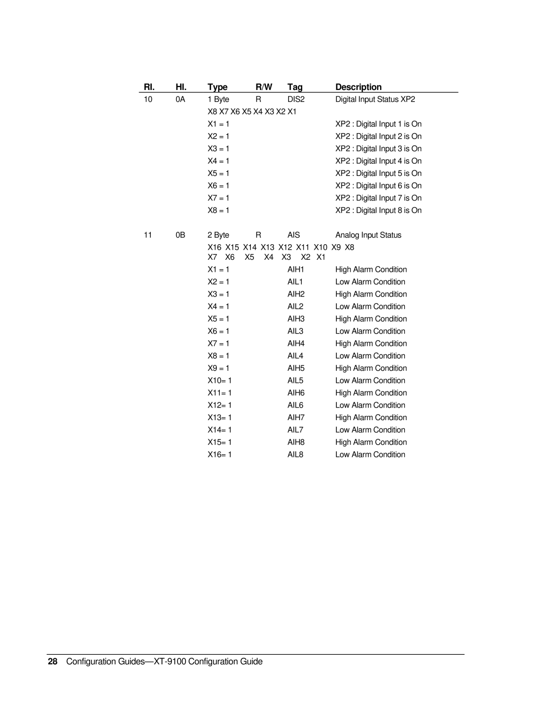
10 | 0A | 1 Byte |
| R | DIS2 | Digital Input Status XP2 | ||
|
| X8 X7 X6 X5 X4 X3 X2 X1 |
|
| ||||
|
| X1 = 1 |
|
|
|
| XP2 : Digital Input 1 is On | |
|
| X2 = 1 |
|
|
|
| XP2 : Digital Input 2 is On | |
|
| X3 = 1 |
|
|
|
| XP2 : Digital Input 3 is On | |
|
| X4 = 1 |
|
|
|
| XP2 : Digital Input 4 is On | |
|
| X5 = 1 |
|
|
|
| XP2 : Digital Input 5 is On | |
|
| X6 = 1 |
|
|
|
| XP2 : Digital Input 6 is On | |
|
| X7 = 1 |
|
|
|
| XP2 : Digital Input 7 is On | |
|
| X8 = 1 |
|
|
|
| XP2 : Digital Input 8 is On | |
11 | 0B | 2 Byte |
| R | AIS |
| Analog Input Status | |
|
| X16 X15 X14 X13 X12 X11 X10 X9 X8 | ||||||
|
| X7 | X6 | X5 | X4 | X3 | X2 | X1 |
|
| X1 = 1 |
|
| AIH1 | High Alarm Condition | ||
|
| X2 = 1 |
|
| AIL1 | Low Alarm Condition | ||
|
| X3 = 1 |
|
| AIH2 | High Alarm Condition | ||
|
| X4 = 1 |
|
| AIL2 | Low Alarm Condition | ||
|
| X5 = 1 |
|
| AIH3 | High Alarm Condition | ||
|
| X6 = 1 |
|
| AIL3 | Low Alarm Condition | ||
|
| X7 = 1 |
|
| AIH4 | High Alarm Condition | ||
|
| X8 = 1 |
|
| AIL4 | Low Alarm Condition | ||
|
| X9 = 1 |
|
| AIH5 | High Alarm Condition | ||
|
| X10= 1 |
|
| AIL5 | Low Alarm Condition | ||
|
| X11= 1 |
|
| AIH6 | High Alarm Condition | ||
|
| X12= 1 |
|
| AIL6 | Low Alarm Condition | ||
|
| X13= 1 |
|
| AIH7 | High Alarm Condition | ||
|
| X14= 1 |
|
| AIL7 | Low Alarm Condition | ||
|
| X15= 1 |
|
| AIH8 | High Alarm Condition | ||
|
| X16= 1 |
|
| AIL8 | Low Alarm Condition | ||