XT-9100 Extension Module/
XP-910x Expansion Modules
Introduction | The XT-9100 Extension Module and its expansion modules have been |
| designed to provide additional input and output capacity within Metasys® |
| Networks and specifically for the DX-9100 Extended Digital Controller. |
| The XT-9100 module provides the communication interface and the |
| XP modules provide the analog and digital inputs and outputs. |
A Supervisory System communicates with an XT-9100 via the N2 Bus or Bus 91*. Each XT-9100, depending on its expansion module combination, can have up to 16 inputs/outputs, eight of which may be analog.
The DX-9100 communicates with the XT-9100 via the XT-Bus, and when the DX-9100 is connected to an N2 Bus (or Bus 91), data from the XT-9100 is available to a Supervisory System. Up to eight XT-9100 modules can be connected to the XT-Bus. Each XT-9100 provides, depending on the type of the connected XP expansion modules, either eight analog points or eight digital points, extending the input/output of a DX-9100 by up to 64 remote input/outputs. Modules with 16 input/outputs may also be connected, provided that the total number of remote input/output points on the DX-9100 does not exceed 64.
Configuration of the XT-9100 is achieved by using a personal computer with GX-9100 Graphic Configuration Software (GX Tool) supplied by Johnson Controls. When the serial interface of the XT-9100 is connected directly to the N2 Bus (Bus 91), the GX-9100 will download and upload configurations over the N2 Bus (Bus 91). When the serial interface of the XT-9100 is connected to the XT Bus, the GX-9100 will download and upload configurations via the N2 Bus (Bus 91) connected to the DX-9100 to which the XT-Bus is connected. The DX-9100 retransmits configuration data to the XT-9100 on its XT-Bus.
R S485 | E X P | X P | + 1 5 V | EX P |
A B C A B C A D D R E S S | | A I1 A I2 A I3 A I4 | |
| | | |
| | | | | | | | | | | max | | |
| | | | | | | | | | | | |
| | | | | | | | | | | AO 7 | | |
P o w e r | | | | | | | min | | |
| | | | | | | | |
| | | | | | m ax | | |
R D | | | | | | | | |
| | | | | | AO 8 | | |
T D | | | | | | | min |
X T 91 0 0 | | | | | | | | X P 9 1 0 2 |
| |
F U S E
C O M 2 4 V 
A I5 A I6 V | | A O 7 | | A O 8 C | 2 4V |
| |
xt910x
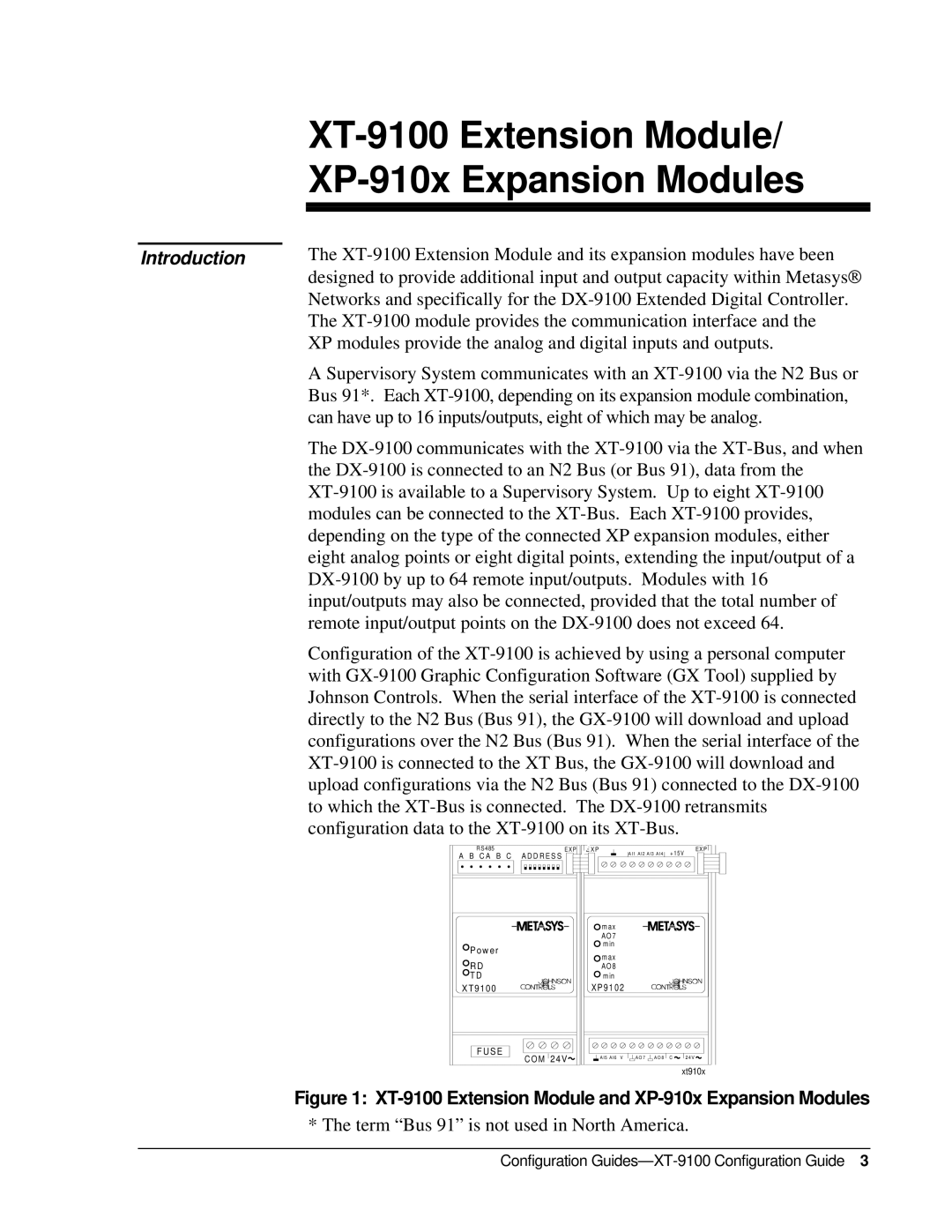
Figure 1: XT-9100 Extension Module and XP-910x Expansion Modules
* The term “Bus 91” is not used in North America.
Configuration Guides—XT-9100 Configuration Guide 3