GF 100 DV II Nordic QT
GF 200 DV II Lillehammer
Gas Conversion Procedure
1.Turn off gas supply to stove.
2.Remove the stove Top Plate (3).
3.GF 100 DV II Only: Remove the front plate from the stove. Pull the casting straight up and out away from the side panels. Pull the panel upward with one hand while the other pushes against the top of the firebox.
4.Release the trunk latches at the top of the firebox. Carefully lift the glass frame up and out.
5.Remove the Log Set using care not to scratch or damage logs.
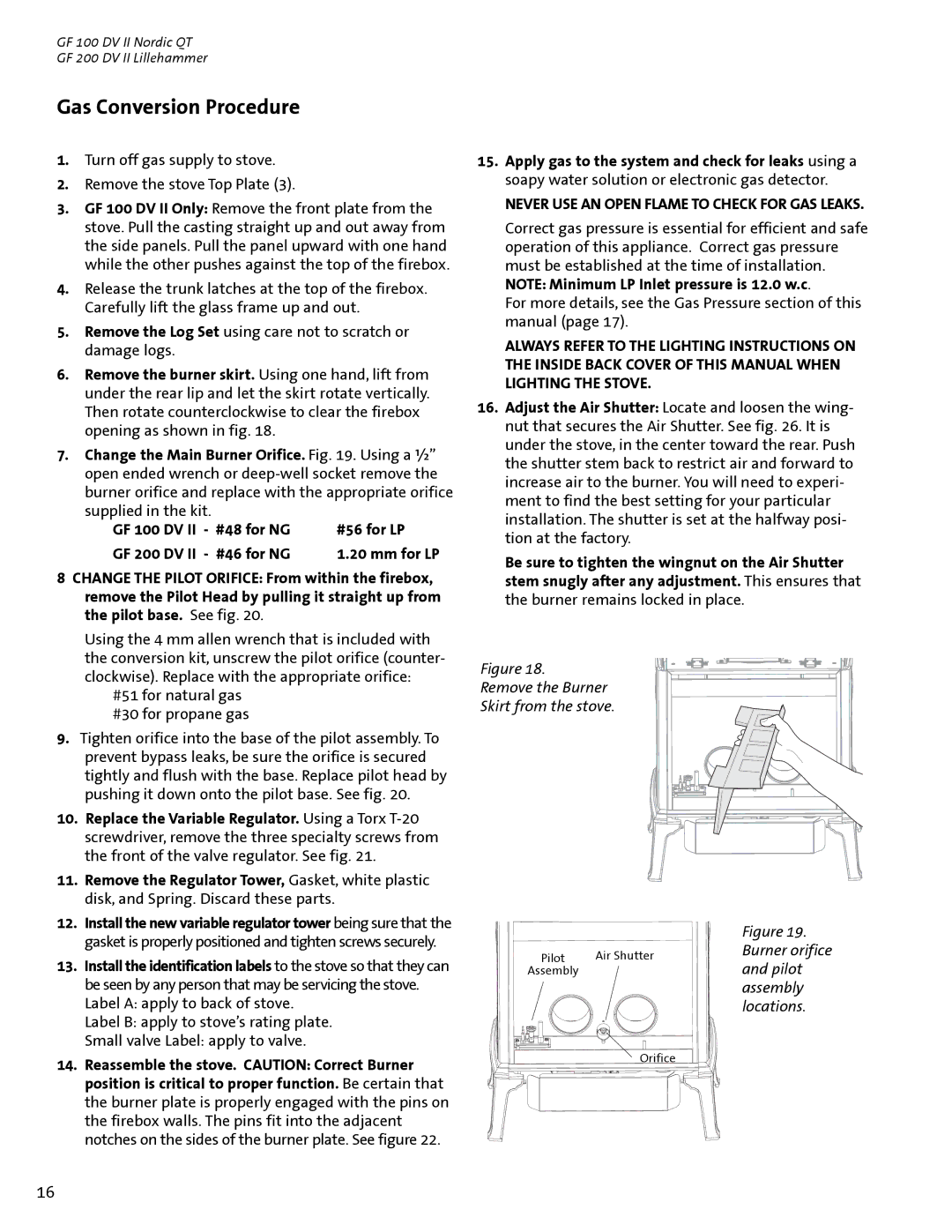
6.Remove the burner skirt. Using one hand, lift from under the rear lip and let the skirt rotate vertically. Then rotate counterclockwise to clear the firebox opening as shown in fig. 18.
7.Change the Main Burner Orifice. Fig. 19. Using a ½” open ended wrench or
GF 100 DV II - #48 for NG | #56 for LP |
GF 200 DV II - #46 for NG | 1.20 mm for LP |
8CHANGE THE PILOT ORIFICE: From within the firebox, remove the Pilot Head by pulling it straight up from the pilot base. See fig. 20.
Using the 4 mm allen wrench that is included with the conversion kit, unscrew the pilot orifice (counter- clockwise). Replace with the appropriate orifice:
#51 for natural gas #30 for propane gas
9.Tighten orifice into the base of the pilot assembly. To prevent bypass leaks, be sure the orifice is secured tightly and flush with the base. Replace pilot head by pushing it down onto the pilot base. See fig. 20.
10.Replace the Variable Regulator. Using a Torx
11.Remove the Regulator Tower, Gasket, white plastic disk, and Spring. Discard these parts.
12.Install the new variable regulator tower being sure that the gasket is properly positioned and tighten screws securely.
13.Install the identification labels to the stove so that they can be seen by any person that may be servicing the stove. Label A: apply to back of stove.
Label B: apply to stove’s rating plate.
Small valve Label: apply to valve.
14.Reassemble the stove. CAUTION: Correct Burner position is critical to proper function. Be certain that the burner plate is properly engaged with the pins on the firebox walls. The pins fit into the adjacent notches on the sides of the burner plate. See figure 22.
15.Apply gas to the system and check for leaks using a soapy water solution or electronic gas detector.
NEVER USE AN OPEN FLAME TO CHECK FOR GAS LEAKS.
Correct gas pressure is essential for efficient and safe operation of this appliance. Correct gas pressure must be established at the time of installation. NOTE: Minimum LP Inlet pressure is 12.0 w.c.
For more details, see the Gas Pressure section of this manual (page 17).
ALWAYS REFER TO THE LIGHTING INSTRUCTIONS ON THE INSIDE BACK COVER OF THIS MANUAL WHEN LIGHTING THE STOVE.
16.Adjust the Air Shutter: Locate and loosen the wing- nut that secures the Air Shutter. See fig. 26. It is under the stove, in the center toward the rear. Push the shutter stem back to restrict air and forward to increase air to the burner. You will need to experi- ment to find the best setting for your particular installation. The shutter is set at the halfway posi- tion at the factory.
Be sure to tighten the wingnut on the Air Shutter stem snugly after any adjustment. This ensures that the burner remains locked in place.
Figure 18.
Remove the Burner
Skirt from the stove.
|
| Figure 19. | |
Pilot | Air Shutter | Burner orifice | |
and pilot | |||
Assembly |
| ||
|
| assembly | |
|
| locations. | |
| Orifice |
|
16