![]()
![]() Pilot Head
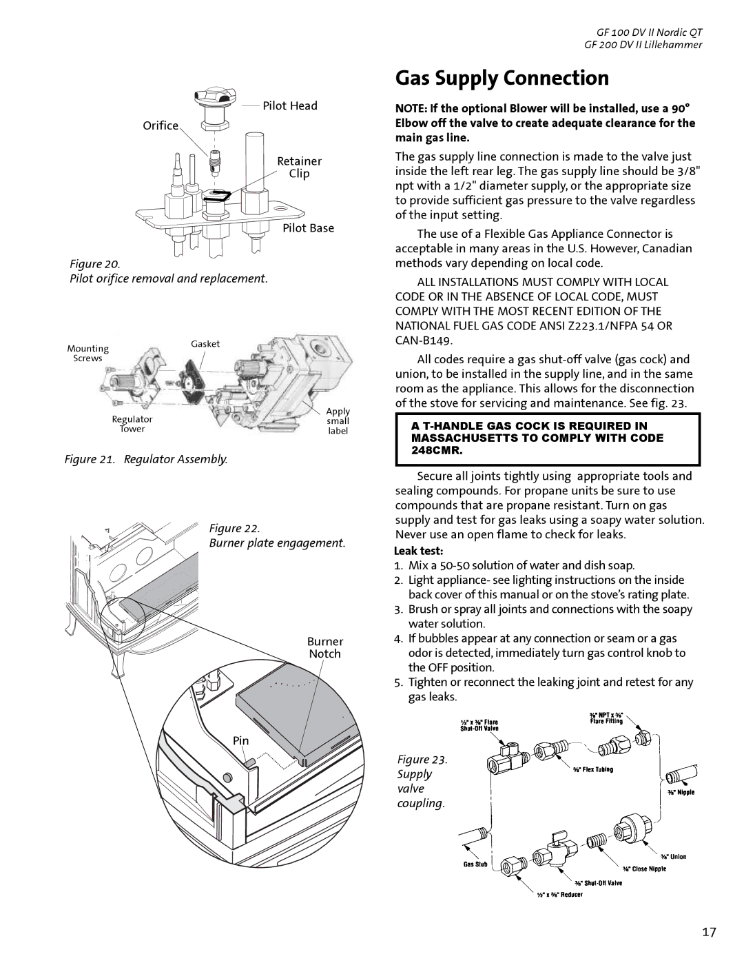
Pilot Head
Orifice
Retainer
Clip
Pilot Base
Figure 20.
Pilot orifice removal and replacement.
Mounting | Gasket |
| |
Screws |
|
Regulator | Apply |
small | |
Tower | label |
Figure 21. Regulator Assembly.
Figure 22.
Burner plate engagement.
Burner
Notch
Pin
GF 100 DV II Nordic QT
GF 200 DV II Lillehammer
Gas Supply Connection
NOTE: If the optional Blower will be installed, use a 90° Elbow off the valve to create adequate clearance for the main gas line.
The gas supply line connection is made to the valve just inside the left rear leg. The gas supply line should be 3/8" npt with a 1/2" diameter supply, or the appropriate size to provide sufficient gas pressure to the valve regardless of the input setting.
The use of a Flexible Gas Appliance Connector is acceptable in many areas in the U.S. However, Canadian methods vary depending on local code.
ALL INSTALLATIONS MUST COMPLY WITH LOCAL CODE OR IN THE ABSENCE OF LOCAL CODE, MUST COMPLY WITH THE MOST RECENT EDITION OF THE NATIONAL FUEL GAS CODE ANSI Z223.1/NFPA 54 OR
All codes require a gas
A
Secure all joints tightly using appropriate tools and sealing compounds. For propane units be sure to use compounds that are propane resistant. Turn on gas supply and test for gas leaks using a soapy water solution. Never use an open flame to check for leaks.
Leak test:
1.Mix a 50-50 solution of water and dish soap.
2.Light appliance- see lighting instructions on the inside back cover of this manual or on the stove’s rating plate.
3.Brush or spray all joints and connections with the soapy water solution.
4.If bubbles appear at any connection or seam or a gas odor is detected, immediately turn gas control knob to the OFF position.
5.Tighten or reconnect the leaking joint and retest for any gas leaks.
Figure 23. Supply valve coupling.
17