GF 100 DV II Nordic QT
GF 200 DV II Lillehammer
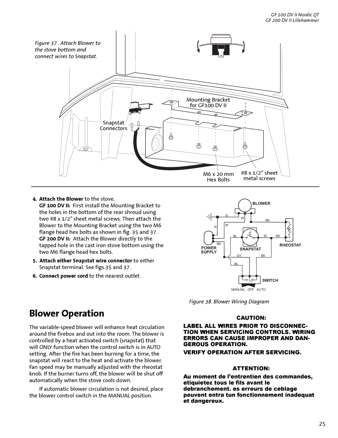
Figure 37 . Attach Blower to the stove bottom and connect wires to Snapstat.
Mounting Bracket
for GF100 DV II
Snapstat
Connectors
M6 x 20 mm | #8 x 1/2” sheet |
Hex Bolts | metal screws |
|
|
4. Attach the Blower to the stove. |
GF 100 DV II: First install the Mounting Bracket to |
the holes in the bottom of the rear shroud using |
BLOWER
two #8 x 1/2” sheet metal screws. Then attach the |
Blower to the Mounting Bracket using the two M6 |
flange head hex bolts as shown in fig. 35 and 37. |
GF 200 DV II: Attach the Blower directly to the |
G
G | W |
|
| BK | |
|
|
W
BL | W | BK |
tapped hole in the cast iron stove bottom using the |
two M6 flange head hex bolts. |
BK
POWER SUPPLY
SNAPSTAT
RHEOSTAT
5. | Attach either Snapstat wire connector to either |
| Snapstat terminal. See figs.35 and 37. |
6. | Connect power cord to the nearest outlet. |
Blower Operation
The
If automatic blower circulation is not desired, place the blower control switch in the MANUAL position.
GYBK
BL
SWITCH
MANUAL OFF AUTO
Figure 38. Blower Wiring Diagram
CAUTION:
LABEL ALL WIRES PRIOR TO DISCONNEC- TION WHEN SERVICING CONTROLS. WIRING ERRORS CAN CAUSE IMPROPER AND DAN- GEROUS OPERATION.
VERIFY OPERATION AFTER SERVICING.
ATTENTION:
Au moment de l’entrentien des commandes, etiquietez tous le fils avant le debranchement. es erreurs de ceblage peuvent entra tun fonctionnement inadequat et dangereux.
25