GF 100 DV II Nordic QT GF 200 DV II Lillehammer
Venting Through a Fireplace
Co-linear Vent Installation
This appliance may be vented through a masonry or Class A prefabricated chimney using a
These installation requirements must be followed:
1.Prior to the installation the chimney flue must be thoroughly cleaned and inspected by a qualified chimney service person.
2.In a masonry chimney, a fireclay liner must be present the entire length of the chimney.
3.Prefabricated chimneys must be UL 103 or ULC
4.No appliance can be installed into a chimney flue serving any other appliance of any kind.
5.THE AIR INTAKE FLEX PIPE MUST EXTEND BEYOND THE DAMPER AREA OF THE FIREPLACE. If the intake flex duct does not extend the full length of the chimney and connect to both the unit and the termination cap, A METAL BLOCK OFF PLATE MUST BE CON-
STRUCTED AND INSTALLED ABOVE THE UNIT PRIOR TO THE END OF THE INTAKE FLEX AND MUST COM- PLETELY SEAL THE CHIMNEY FLUE FROM THE ROOM.
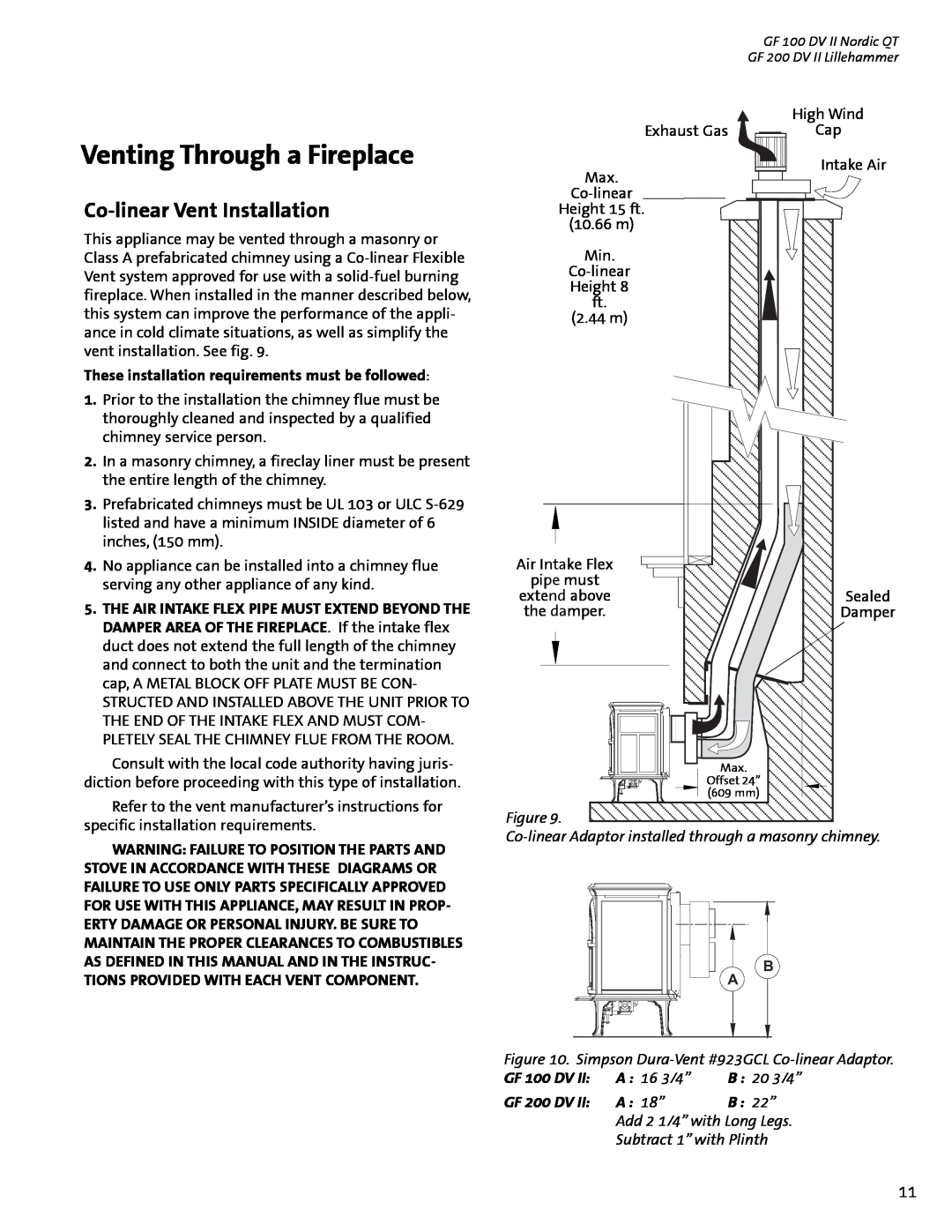
Exhaust Gas
Max.
Height 15 ft.
(10.66 m)
Min.
Height 8
ft.
(2.44 m)
Air Intake Flex
pipe must
extend above the damper.
High Wind
Cap
Intake Air
Sealed
Damper
Consult with the local code authority having juris- diction before proceeding with this type of installation.
Refer to the vent manufacturer’s instructions for specific installation requirements.
WARNING: FAILURE TO POSITION THE PARTS AND STOVE IN ACCORDANCE WITH THESE DIAGRAMS OR FAILURE TO USE ONLY PARTS SPECIFICALLY APPROVED FOR USE WITH THIS APPLIANCE, MAY RESULT IN PROP- ERTY DAMAGE OR PERSONAL INJURY. BE SURE TO MAINTAIN THE PROPER CLEARANCES TO COMBUSTIBLES
Max.
Offset 24”
(609 mm)
Figure 9.
AS DEFINED IN THIS MANUAL AND IN THE INSTRUC- TIONS PROVIDED WITH EACH VENT COMPONENT.
A
B
Figure 10. Simpson
GF 100 DV II: | A : 16 3/4” | B : 20 3/4” |
GF 200 DV II: | A : 18” | B : 22” |
Add 2 1/4” with Long Legs.
Subtract 1” with Plinth
11