High Altitude Orifice Chart
GF 200 DV II Only
Elevation | Fuel | Orifice | Part No. | |
Size | ||||
|
|
| ||
0 - 2000 ft. | Natural Gas | #46 | 220975 | |
(0 - 610 m) | Propane | 1.20 mm | 221185 | |
|
|
|
| |
2001 - 4500 ft. | Natural Gas | #47 | 220976 | |
(611 - 1370 m) | Propane | #56 | 129466 | |
|
|
|
|
Derating Procedure:
1.To derate this unit, install the appropriate orifice per the High Altitude chart.
2.Remove the Burner Skirt and Burner Plate to expose the main burner orifice.
3.Using a 1/2” open ended wrench or a
4.Replace with the appropriate orifice from the high altitude kit.
5.Be sure to apply the high altitude conversion label provided to the rating plate on the appliance.
THIS STOVE HAS BEEN CONVERTED FOR USE AT AN ALTITUDE OF: ________________
Orifice Size: ____________ Manifold Press. _____
Input Btu/Hr. ___________ Fuel Type __________
Date of Conversion ___________
Figure 25. This label must be filled out and applied to the appliance by the installer.
GF 100 DV II Nordic QT
GF 200 DV II Lillehammer
Flame Appearance -
Air Shutter Adjustment
WARNING: AIR SHUTTER ADJUSTMENTS SHOULD ONLY BE PERFORMED BY A QUALIFIED PROFESSIONAL SERVICE TECHNICIAN.
The air shutter setting at the burner orifice can be adjusted to achieve the desired flame appearance. The shutter is set in the
Too much air - the appliance will generate a flame that is blue and transparent, or an “anemic” flame.
Not enough air - the burner will generate very long yellow flames resulting in soot. Sooting produces black deposits on the logs, on the inside walls of the appliance, and potentially on the exterior termination cap.
Sooting is caused by incomplete combustion in the flames and lack of combustion air entering the air shutter opening. Open the shutter setting to allow more air.
To adjust the air shutter:
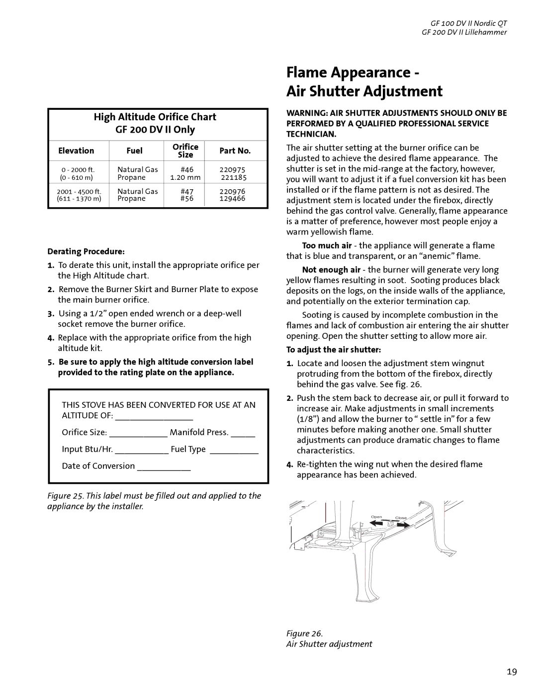
1.Locate and loosen the adjustment stem wingnut protruding from the bottom of the firebox, directly behind the gas valve. See fig. 26.
2.Push the stem back to decrease air, or pull it forward to increase air. Make adjustments in small increments (1/8”) and allow the burner to “ settle in” for a few minutes before making another one. Small shutter adjustments can produce dramatic changes to flame characteristics.
4.
Open Close
Figure 26.
Air Shutter adjustment
19