GF 100 DV II Nordic QT GF 200 DV II Lillehammer
Venting Requirements
Both stoves may be installed with a vertical or horizontal termination and must conform to the configuration requirements described in this section. Vent components from the manufacturers listed below are approved for use:
•Simpson
•Selkirk Metalbestos
•Security Vent Ltd.
•Amerivent Corporation
Use parts of one manufacturer only - DO NOT MIX VENT COMPONENTS FROM DIFFERENT MANUFACTURERS IN THE SAME SYSTEM.
Installation of any components not manufactured or approved by Jøtul or failure to meet all clearance require- ments will void all warranties and could result in prop- erty damage, bodily injury, or serious fire.
The approved vent configurations described in this manual are derived from extensive testing under con- trolled laboratory conditions. Gas appliance performance can be negatively affected by variables present in the installation environment, i.e: atmospheric pressure, strong prevailing winds, adjacent structures and trees, snow accumulation, etc. These conditions should be taken into consideration by the installer and stove owner when planning the vent system design.
IMPORTANT
•JOINT SEALING REQUIREMENT: APPLY A 1/8” BEAD OF
VENT PIPE. THE CEMENT SHOULD FORM A SEAL BETWEEN THE INNER AND OUTER PIPES.
• NEVER MODIFY ANY VENTING COMPONENT, OR USE ANY DAMAGED VENTING PRODUCT.
• THE GAS APPLIANCE AND VENT SYSTEM MUST BE VENTED DIRECTLY TO THE OUTSIDE OF THE BUILDING AND NEVER ATTACHED TO
A CHIMNEY SERVING A SOLID FUEL OR GAS BURNING APPLIANCE. EACH DIRECT VENT GAS APPLIANCE MUST HAVE ITS OWN SEPARATE VENT SYSTEM. COMMON VENT SYSTEMS ARE PROHIBITED.
•IF VENTING SYSTEM IS DISASSEMBLED FOR ANY REASON, REINSTALL PER THE INSTRUCTIONS PROVIDED FOR THE INITIAL INSTALLATION.
Intake Air Restriction
You may need to restrict air intake to the burner, depend- ing on the stove vent configuration. Two Side Restrictor Plates and one Rear Restrictor Plate are included in the Miscellaneous Kit for this purpose. Use the following guidelines to determine the proper restriction, if any, for your installation.
Horizontal Termination
No air restriction should be necessary. Do not install the restrictor plates.
Vertical Termination
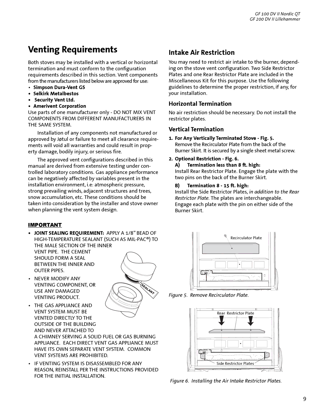
1.For Any Vertically Terminated Stove - Fig. 5. Remove the Recirculator Plate from the back of the Burner Skirt. It is secured by a single sheet metal screw.
2.Optional Restriction - Fig. 6.
A)Termination less than 8 ft. high:
Install Rear Restrictor Plate. Engage the plate with the two pins on the back of the Burner Skirt.
B)Termination 8 - 15 ft. high:
Install the Side Restrictor Plates, in addition to the Rear Restrictor Plate. The plates are interchangeable. Engage each plate with the pin on either side of the Burner Skirt.
Recirculator Plate
Figure 5. Remove Recirculator Plate.
Rear Restrictor Plate
Side Restrictor Plates
Figure 6. Installing the Air Intake Restrictor Plates.
9