3.1.14 Removing the panel board (See Figs.20 and 21)
•Remove the panel assembly.
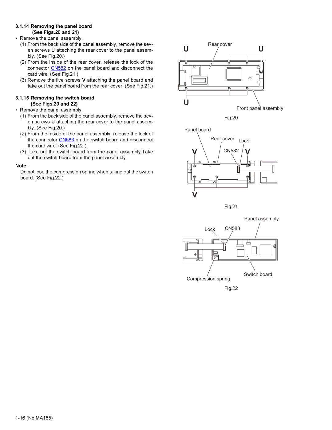
(1)From the back side of the panel assembly, remove the sev- en screws U attaching the rear cover to the panel assem- bly. (See Fig.20.)
(2)From the inside of the rear cover, release the lock of the connector CN582 on the panel board and disconnect the card wire. (See Fig.21.)
(3)Remove the five screws V attaching the panel board and take out the panel board from the rear cover. (See Fig.21.)
3.1.15Removing the switch board (See Figs.20 and 22)
•Remove the panel assembly.
(1)From the back side of the panel assembly, remove the sev- en screws U attaching the rear cover to the panel assem- bly. (See Fig.20.)
(2)From the inside of the panel assembly, release the lock of the connector CN583 on the switch board and disconnect the card wire. (See Fig.22.)
(3)Take out the switch board from the panel assembly.Take out the switch board from the panel assembly.
Note:
Do not lose the compression spring when taking out the switch board. (See Fig.22.)
Rear cover
UU
U
Front panel assembly
Fig.20
Panel board
Rear cover Lock
V | CN582 V |
V
Fig.21
Panel assembly
Lock CN583
Switch board
Compression spring
Fig.22