4.6.9 Monitor adjustment
![]() When adjusting, switch on the main unit and insert a test disc
When adjusting, switch on the main unit and insert a test disc
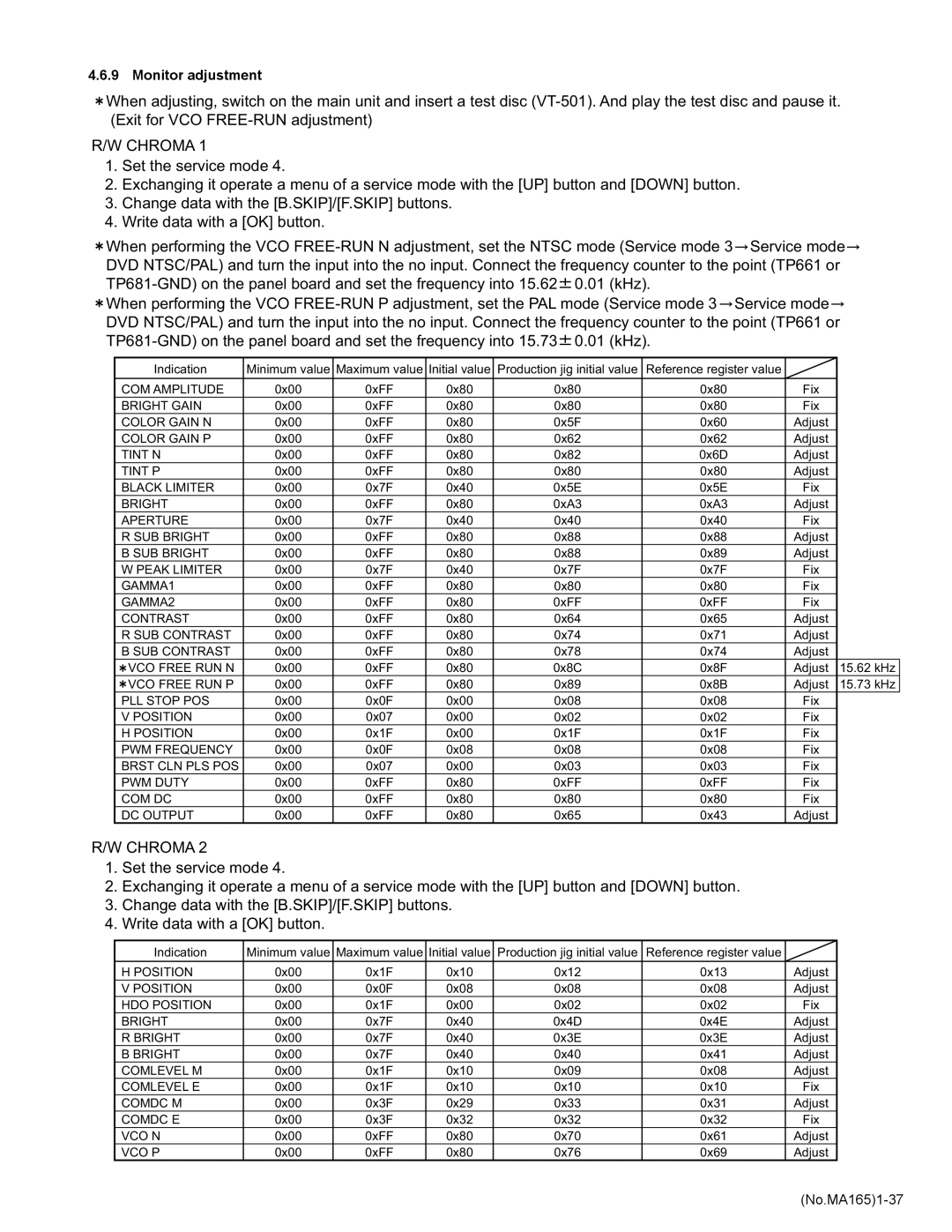
R/W CHROMA 1
1.Set the service mode 4.
2.Exchanging it operate a menu of a service mode with the [UP] button and [DOWN] button.
3.Change data with the [B.SKIP]/[F.SKIP] buttons.
4.Write data with a [OK] button.
![]() When performing the VCO
When performing the VCO ![]() Service mode
Service mode![]() DVD NTSC/PAL) and turn the input into the no input. Connect the frequency counter to the point (TP661 or
DVD NTSC/PAL) and turn the input into the no input. Connect the frequency counter to the point (TP661 or ![]() 0.01 (kHz).
0.01 (kHz).
Indication | Minimum value | Maximum value | Initial value | Production jig initial value | Reference register value |
|
|
|
|
|
|
|
|
|
|
COM AMPLITUDE | 0x00 | 0xFF | 0x80 | 0x80 | 0x80 | Fix |
|
BRIGHT GAIN | 0x00 | 0xFF | 0x80 | 0x80 | 0x80 | Fix |
|
COLOR GAIN N | 0x00 | 0xFF | 0x80 | 0x5F | 0x60 | Adjust |
|
COLOR GAIN P | 0x00 | 0xFF | 0x80 | 0x62 | 0x62 | Adjust |
|
TINT N | 0x00 | 0xFF | 0x80 | 0x82 | 0x6D | Adjust |
|
TINT P | 0x00 | 0xFF | 0x80 | 0x80 | 0x80 | Adjust |
|
BLACK LIMITER | 0x00 | 0x7F | 0x40 | 0x5E | 0x5E | Fix |
|
BRIGHT | 0x00 | 0xFF | 0x80 | 0xA3 | 0xA3 | Adjust |
|
APERTURE | 0x00 | 0x7F | 0x40 | 0x40 | 0x40 | Fix |
|
R SUB BRIGHT | 0x00 | 0xFF | 0x80 | 0x88 | 0x88 | Adjust |
|
B SUB BRIGHT | 0x00 | 0xFF | 0x80 | 0x88 | 0x89 | Adjust |
|
W PEAK LIMITER | 0x00 | 0x7F | 0x40 | 0x7F | 0x7F | Fix |
|
GAMMA1 | 0x00 | 0xFF | 0x80 | 0x80 | 0x80 | Fix |
|
GAMMA2 | 0x00 | 0xFF | 0x80 | 0xFF | 0xFF | Fix |
|
CONTRAST | 0x00 | 0xFF | 0x80 | 0x64 | 0x65 | Adjust |
|
R SUB CONTRAST | 0x00 | 0xFF | 0x80 | 0x74 | 0x71 | Adjust |
|
B SUB CONTRAST | 0x00 | 0xFF | 0x80 | 0x78 | 0x74 | Adjust |
|
VCO FREE RUN N | 0x00 | 0xFF | 0x80 | 0x8C | 0x8F | Adjust | 15.62 kHz |
VCO FREE RUN P | 0x00 | 0xFF | 0x80 | 0x89 | 0x8B | Adjust | 15.73 kHz |
PLL STOP POS | 0x00 | 0x0F | 0x00 | 0x08 | 0x08 | Fix |
|
V POSITION | 0x00 | 0x07 | 0x00 | 0x02 | 0x02 | Fix |
|
H POSITION | 0x00 | 0x1F | 0x00 | 0x1F | 0x1F | Fix |
|
PWM FREQUENCY | 0x00 | 0x0F | 0x08 | 0x08 | 0x08 | Fix |
|
BRST CLN PLS POS | 0x00 | 0x07 | 0x00 | 0x03 | 0x03 | Fix |
|
PWM DUTY | 0x00 | 0xFF | 0x80 | 0xFF | 0xFF | Fix |
|
COM DC | 0x00 | 0xFF | 0x80 | 0x80 | 0x80 | Fix |
|
DC OUTPUT | 0x00 | 0xFF | 0x80 | 0x65 | 0x43 | Adjust |
|
R/W CHROMA 2
1.Set the service mode 4.
2.Exchanging it operate a menu of a service mode with the [UP] button and [DOWN] button.
3.Change data with the [B.SKIP]/[F.SKIP] buttons.
4.Write data with a [OK] button.
Indication | Minimum value | Maximum value | Initial value | Production jig initial value | Reference register value |
|
|
|
|
|
|
|
|
H POSITION | 0x00 | 0x1F | 0x10 | 0x12 | 0x13 | Adjust |
V POSITION | 0x00 | 0x0F | 0x08 | 0x08 | 0x08 | Adjust |
HDO POSITION | 0x00 | 0x1F | 0x00 | 0x02 | 0x02 | Fix |
BRIGHT | 0x00 | 0x7F | 0x40 | 0x4D | 0x4E | Adjust |
R BRIGHT | 0x00 | 0x7F | 0x40 | 0x3E | 0x3E | Adjust |
B BRIGHT | 0x00 | 0x7F | 0x40 | 0x40 | 0x41 | Adjust |
COMLEVEL M | 0x00 | 0x1F | 0x10 | 0x09 | 0x08 | Adjust |
COMLEVEL E | 0x00 | 0x1F | 0x10 | 0x10 | 0x10 | Fix |
COMDC M | 0x00 | 0x3F | 0x29 | 0x33 | 0x31 | Adjust |
COMDC E | 0x00 | 0x3F | 0x32 | 0x32 | 0x32 | Fix |
VCO N | 0x00 | 0xFF | 0x80 | 0x70 | 0x61 | Adjust |
VCO P | 0x00 | 0xFF | 0x80 | 0x76 | 0x69 | Adjust |
