3.1.3 Removing the top chassis assembly (See Figs.3 to 6)
•Remove the panel assembly and side heat sink.
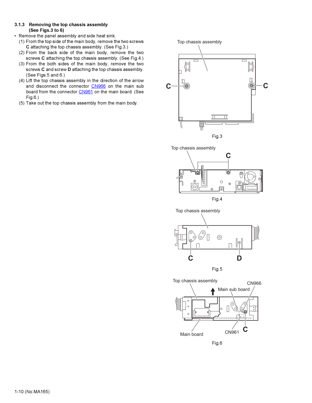
(1)From the top side of the main body, remove the two screws C attaching the top chassis assembly. (See Fig.3.)
(2)From the back side of the main body, remove the two screws C attaching the top chassis assembly. (See Fig.4.)
(3)From the both sides of the main body, remove the two screws C and screw D attaching the top chassis assembly. (See Figs.5 and 6.)
(4)Lift the top chassis assembly in the direction of the arrow and disconnect the connector CN966 on the main sub board from the connector CN961 on the main board. (See Fig.6.)
(5)Take out the top chassis assembly from the main body.
Top chassis assembly
C | C |
Fig.3
Top chassis assembly
C
Fig.4
Top chassis assembly
CD
Fig.5
Top chassis assembly
CN966
![]() Main sub board
Main sub board
Main board | CN961 C |
| |
| Fig.6 |