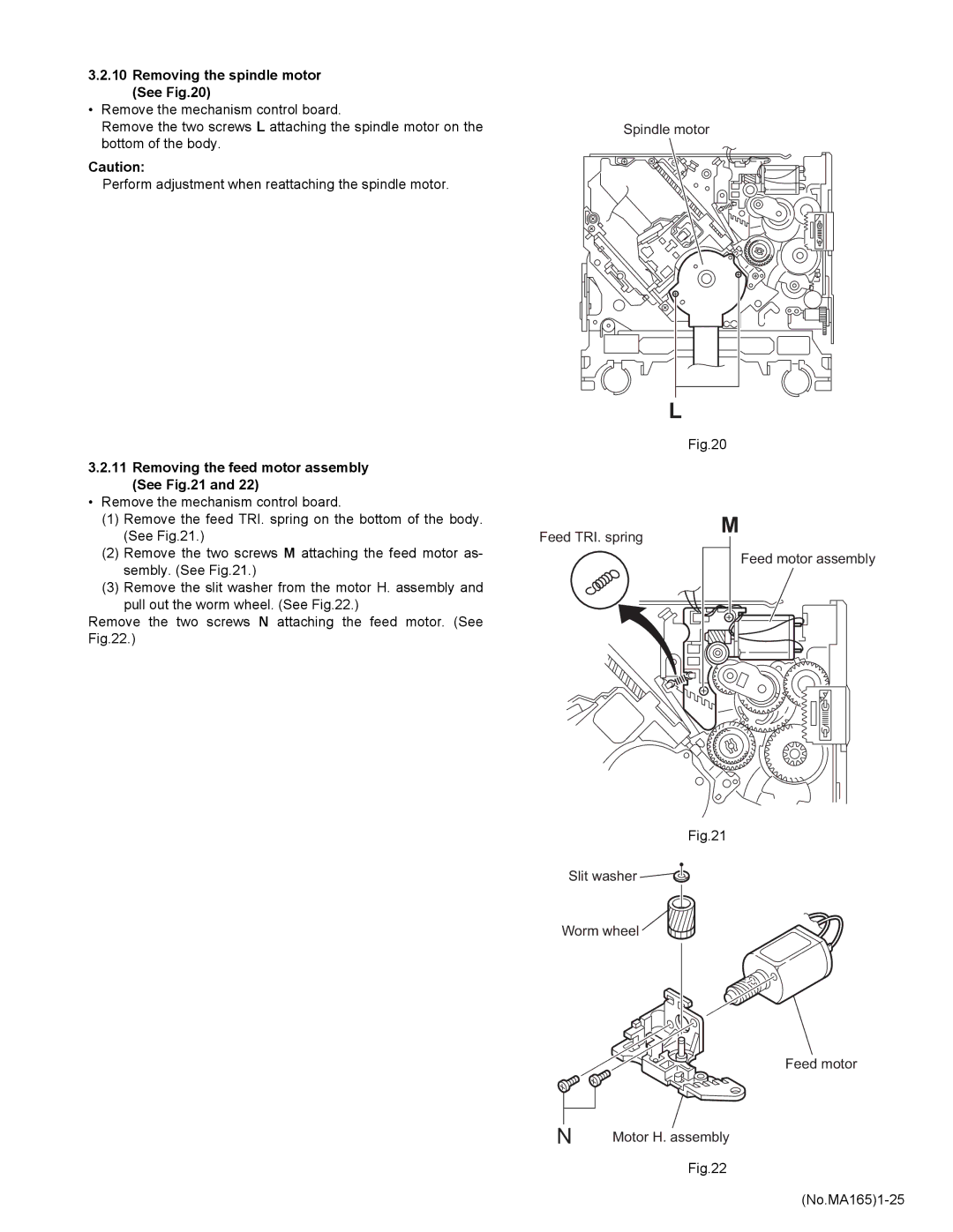
3.2.10Removing the spindle motor (See Fig.20)
• Remove the mechanism control board. |
|
Remove the two screws L attaching the spindle motor on the | Spindle motor |
bottom of the body. |
|
Caution: |
|
Perform adjustment when reattaching the spindle motor. |
|
3.2.11Removing the feed motor assembly (See Fig.21 and 22)
L |
Fig.20 |
•Remove the mechanism control board.
(1)Remove the feed TRI. spring on the bottom of the body. (See Fig.21.)
(2)Remove the two screws M attaching the feed motor as- sembly. (See Fig.21.)
(3)Remove the slit washer from the motor H. assembly and
pull out the worm wheel. (See Fig.22.)
Remove the two screws N attaching the feed motor. (See Fig.22.)
Feed TRI. spring
M
Feed motor assembly
Fig.21
Slit washer
Worm wheel
Feed motor
N | Motor H. assembly |
Fig.22