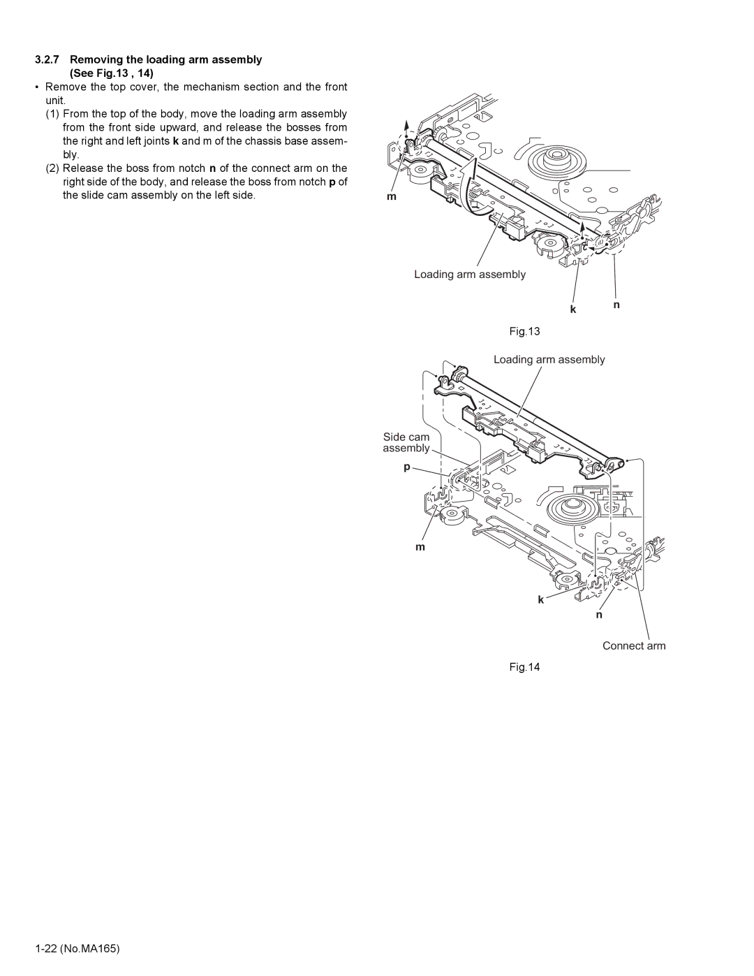
3.2.7 Removing the loading arm assembly (See Fig.13 , 14)
•Remove the top cover, the mechanism section and the front unit.
(1) | From the top of the body, move the loading arm assembly |
|
| from the front side upward, and release the bosses from |
|
| the right and left joints k and m of the chassis base assem- |
|
| bly. |
|
(2) | Release the boss from notch n of the connect arm on the |
|
| right side of the body, and release the boss from notch p of |
|
| the slide cam assembly on the left side. | m |
Loading arm assembly
k n
Fig.13
Loading arm assembly
Side cam assembly
p
m
k![]()
n
Connect arm
Fig.14