3.1.4 Removing the front chassis assembly |
|
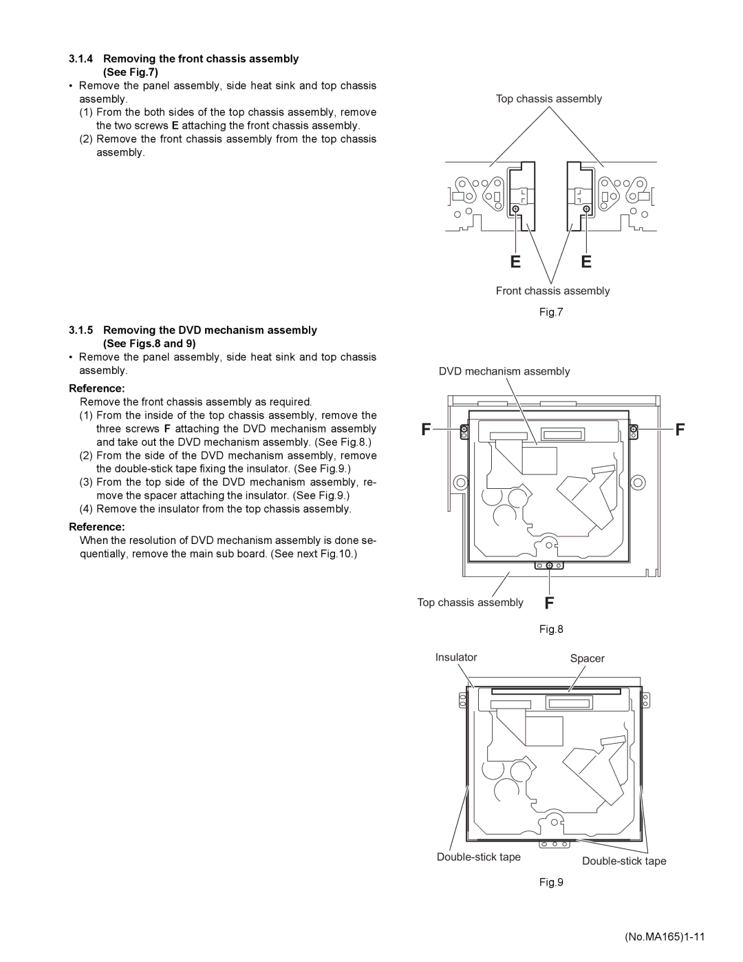
(See Fig.7) |
|
• Remove the panel assembly, side heat sink and top chassis |
|
assembly. | Top chassis assembly |
(1)From the both sides of the top chassis assembly, remove the two screws E attaching the front chassis assembly.
(2)Remove the front chassis assembly from the top chassis assembly.
3.1.5Removing the DVD mechanism assembly (See Figs.8 and 9)
•Remove the panel assembly, side heat sink and top chassis assembly.
Reference:
Remove the front chassis assembly as required.
(1)From the inside of the top chassis assembly, remove the three screws F attaching the DVD mechanism assembly and take out the DVD mechanism assembly. (See Fig.8.)
(2)From the side of the DVD mechanism assembly, remove the
(3)From the top side of the DVD mechanism assembly, re- move the spacer attaching the insulator. (See Fig.9.)
(4)Remove the insulator from the top chassis assembly.
Reference:
When the resolution of DVD mechanism assembly is done se- quentially, remove the main sub board. (See next Fig.10.)
E E
Front chassis assembly
Fig.7
DVD mechanism assembly
F![]()
![]()
![]()
![]() F
F
Top chassis assembly | F |
| Fig.8 |
Insulator | Spacer |
|
Fig.9