SECTION 4
ADJUSTMENT
4.1Test instruments required for adjustment
(1)Digital oscilloscope (100MHz)
(2)Jitter meter
(3)Digital tester
(4)Electric voltmeter
(5)Tracking offset meter
(6)Test Disc : VT501 or VT502
(7)Extension studs :
(8)Extension cable :
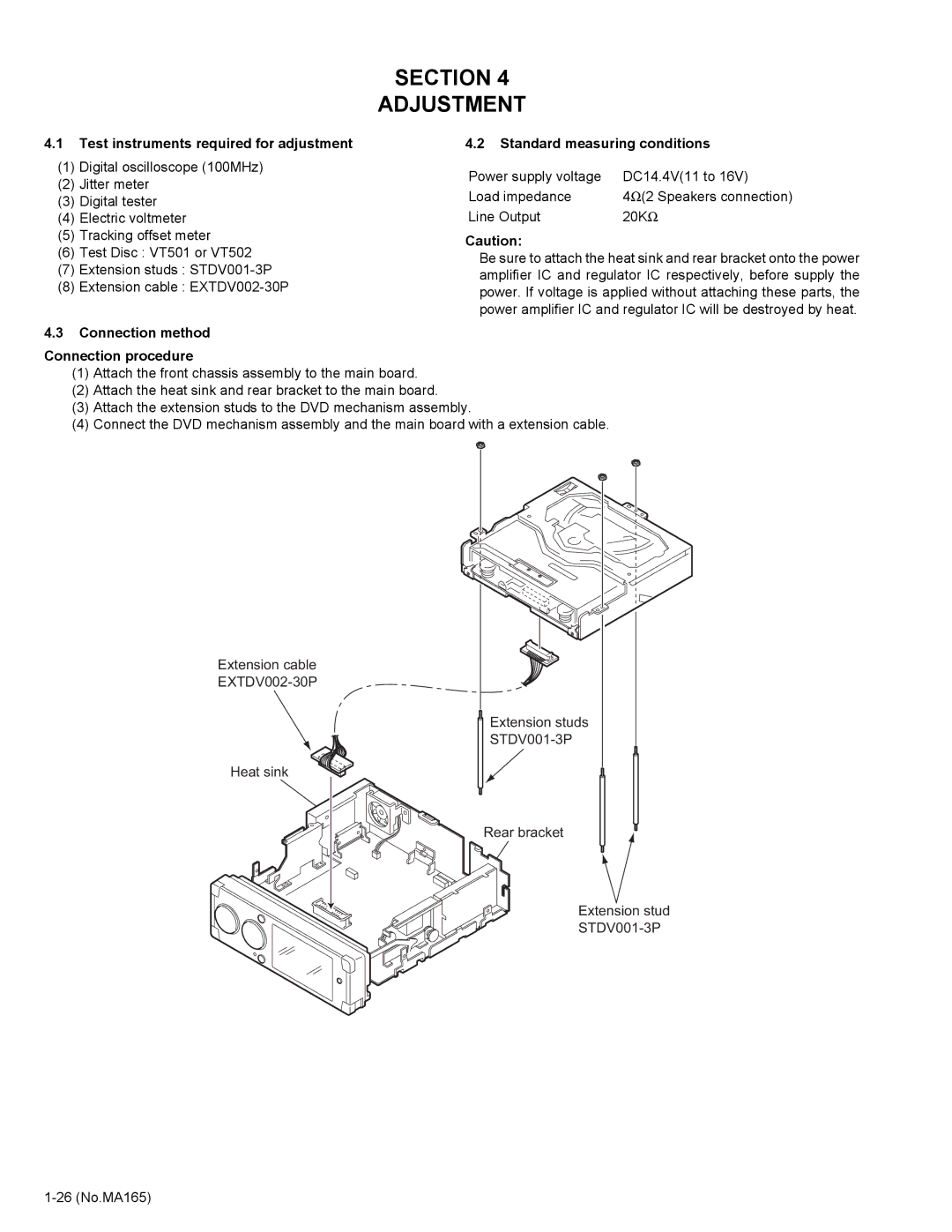
4.3Connection method
4.2Standard measuring conditions
Power supply voltage | DC14.4V(11 to 16V) |
Load impedance | 4Ω (2 Speakers connection) |
Line Output | 20KΩ |
Caution:
Be sure to attach the heat sink and rear bracket onto the power amplifier IC and regulator IC respectively, before supply the power. If voltage is applied without attaching these parts, the power amplifier IC and regulator IC will be destroyed by heat.
Connection procedure
(1)Attach the front chassis assembly to the main board.
(2)Attach the heat sink and rear bracket to the main board.
(3)Attach the extension studs to the DVD mechanism assembly.
(4)Connect the DVD mechanism assembly and the main board with a extension cable.
Extension cable
Extension studs
Heat sink
Rear bracket
Extension stud