18 EN INSTALLING YOUR NEW UNIT |
|
|
| ||||
Basic Connections |
|
| 8 Basic Connection |
| |||
|
| To connect to a TV with | |||||
|
|
|
|
|
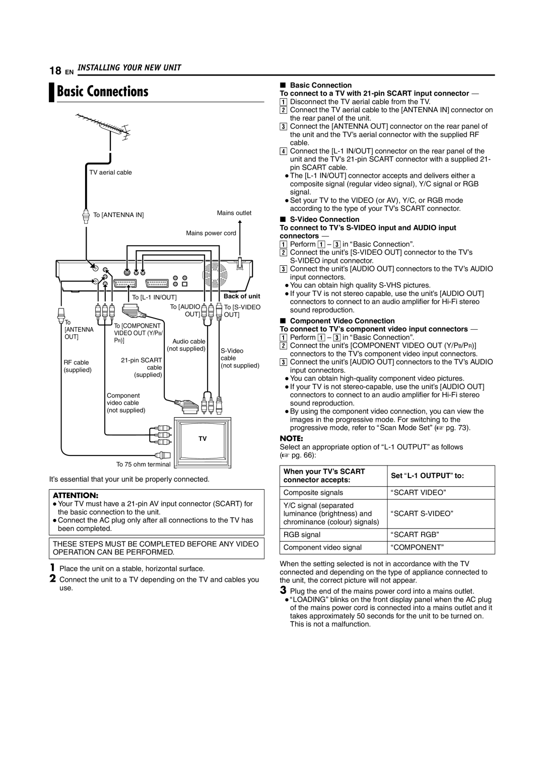
| A Disconnect the TV aerial cable from the TV. | |
|
|
|
|
|
| B Connect the TV aerial cable to the [ANTENNA IN] connector on | |
|
|
|
|
|
| the rear panel of the unit. |
|
|
|
|
|
|
| C Connect the [ANTENNA OUT] connector on the rear panel of | |
|
|
|
|
|
| the unit and the TV’s aerial connector with the supplied RF | |
|
|
|
|
|
| cable. |
|
|
|
|
|
|
| D Connect the | |
|
|
|
|
|
| unit and the TV’s | |
| TV aerial cable |
|
| pin SCART cable. |
| ||
|
|
| ● The | ||||
|
|
|
|
|
| ||
|
|
|
|
|
| composite signal (regular video signal), Y/C signal or RGB | |
|
|
|
|
|
| signal. |
|
|
|
|
|
|
| ● Set your TV to the VIDEO (or AV), Y/C, or RGB mode | |
|
| To [ANTENNA IN] |
| Mains outlet | according to the type of your TV’s SCART connector. | ||
|
|
| 8 |
| |||
|
|
|
|
| |||
|
|
|
|
|
|
| |
|
|
|
| Mains power cord | To connect to TV’s | ||
|
|
|
| connectors ^ |
| ||
|
|
|
|
|
|
| |
|
|
|
|
|
| A Perform A – C in ABasic ConnectionB. | |
|
|
|
|
|
| B Connect the unit’s | |
|
|
|
|
|
|
| |
|
|
|
|
|
| C Connect the unit’s [AUDIO OUT] connectors to the TV’s AUDIO | |
|
|
|
|
|
| input connectors. |
|
|
|
|
|
|
| ● You can obtain high quality | |
|
|
| To | Back of unit | ● If your TV is not stereo capable, use the unit’s [AUDIO OUT] | ||
|
|
| connectors to connect to an audio amplifier for | ||||
|
|
|
| To [AUDIO | To | ||
|
|
|
| sound reproduction. |
| ||
|
|
|
| OUT] | OUT] |
| |
|
|
|
| 8 Component Video Connection | |||
To |
|
| To [COMPONENT |
|
| ||
[ANTENNA |
|
| To connect to TV’s component video input connectors ^ | ||||
VIDEO OUT (Y/PB/ |
|
| |||||
OUT] |
|
|
|
| A Perform A – C in ABasic ConnectionB. | ||
|
| PR)] | Audio cable |
| |||
|
|
|
| B Connect the unit’s [COMPONENT VIDEO OUT (Y/PB/PR)] | |||
|
|
|
| (not supplied) | |||
|
|
|
| connectors to the TV’s component video input connectors. | |||
|
|
|
|
| |||
|
|
|
| cable | |||
RF cable |
|
|
| C Connect the unit’s [AUDIO OUT] connectors to the TV’s AUDIO | |||
|
|
| (not supplied) | ||||
(supplied) |
| cable |
| input connectors. |
| ||
|
|
|
| ||||
| (supplied) |
|
|
| |||
|
|
|
|
| ● You can obtain | ||
|
|
|
|
|
| ||
|
|
|
|
|
| ● If your TV is not | |
|
|
| Component |
|
| connectors to connect to an audio amplifier for | |
|
|
| video cable |
|
| sound reproduction. |
|
|
|
| (not supplied) |
|
| ● By using the component video connection, you can view the | |
|
|
|
|
|
| images in the progressive mode. For switching to the | |
|
|
|
|
|
| progressive mode, refer to AScan Mode SetB (A pg. 73). | |
|
|
|
| TV |
| NOTE: |
|
|
|
|
|
|
| Select an appropriate option of | |
|
|
|
|
|
| (A pg. 66): |
|
|
|
| To 75 ohm terminal |
| When your TV’s SCART |
| |
It’s essential that your unit be properly connected. |
| Set | |||||
| connector accepts: | ||||||
|
| ||||||
ATTENTION: |
| Composite signals | ASCART VIDEOB |
|
|
| |
● Your TV must have a |
| Y/C signal (separated |
|
the basic connection to the unit. |
| luminance (brightness) and | ASCART |
● Connect the AC plug only after all connections to the TV has |
| chrominance (colour) signals) |
|
been completed. |
|
|
|
| RGB signal | ASCART RGBB | |
|
| ||
| |||
THESE STEPS MUST BE COMPLETED BEFORE ANY VIDEO |
| Component video signal | ACOMPONENTB |
OPERATION CAN BE PERFORMED. |
| ||
|
|
| |
| When the setting selected is not in accordance with the TV | ||
|
| ||
1 Place the unit on a stable, horizontal surface. |
| ||
| connected and depending on the type of appliance connected to | ||
2 Connect the unit to a TV depending on the TV and cables you |
| ||
| the unit, the correct picture will not appear. | ||
use. |
| 3 Plug the end of the mains power cord into a mains outlet. | |
● ALOADINGB blinks on the front display panel when the AC plug of the mains power cord is connected into a mains outlet and it takes approximately 50 seconds for the unit to be turned on.
This is not a malfunction.