For safety
Temperature inside the car
To keep discs clean
How to reset your unit
Display window Remote controller-RM-RK50
When an FM stereo broadcast is hard to receive
Manual presetting
Control panel
AM Tuner
Prepare this before installation
FM Tuner
JVC Amplifier
Precautions on power supply and speaker connections
Set L/O Mode to Rear
Basic settings
Enter PSM menu Cancel the display
Demonstration Select an item Adjust
Playing an MP3/WMA disc for KD-G394
Stereo mini plug
Not supplied
Accordingly
Portable audio player, etc
Symptoms Remedies/Causes General
For KD-G394
Instructions
How to reset your unit
How to forcibly eject a disc
Thank you for purchasing a JVC product
Possible performance from the unit
Contents
Main display
Display window
¢ buttons w Control dial Band button
Installing the lithium coin battery CR2025
Standby/on/attenuator button
For FM/AM tuner ⁄ Adjust the volume
@ Adjust the sound as you want. See
To turn off the power
Setting the clock
Manual presetting
Radio operations
Memory
Start searching for a station
Playing a disc in the unit ~ Turn on the power
Disc operations
To stop play and eject the disc
Clock ÔFrequency
Prohibiting disc ejection
Indication, Range
Sound adjustments
Random play Mode
Adjust the volume ⁄ Adjust the sound as you want. See
Operations
Listed in the table on
Select a PSM item
Indications Selectable settings, reference
Maintenance
To keep discs clean
How to handle discs
Moisture condensation
Turning on the power
Turning off the power
More about this unit
Storing stations in memory
General settings-PSM
Disc
Changing the source
Ejecting a disc
Troubleshooting
Specifications
Having Trouble with operation?
Precautions on power supply and speaker connections
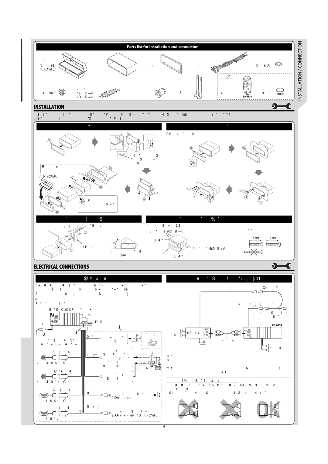
Parts list for installation and connection
Installation IN-DASH Mounting
Removing the unit
√‡ËÕ¡‚¥¬„ȉøøÈ
Typical connections / √‡ËÕ¡µËÕ·ªµ
√µ√« Õªí≠À¢¥- ¢ÈÕß
Instructions Buku Petunjuk
How to reset your unit
Contents
Parts identification
Remote controller RM-RK50
Getting started
Radio operations
Disc operations
Other main functions
Sound adjustments
Operations
Demo
Holding it by the edges
More about this unit
Disc
Troubleshooting
Specifications
Ada Masalah dengan cara Pengoperasian?
English Indonesia
Daftar bagian-bagian untuk pemasangan dan penyambungan
Pemasangan BINGKAI-DALAM Dash
Memindahkan alat penerima
SAMBUNGAN-SAMBUNGAN Listrik
Typical connections / Ciri khas sambungan-sambungan
Pemecahan Masalah
GET0486-005A
How to reset your unit
Operations
Parts identification
Remote controller RM-RK50
Volume level appears
Radio operations
Press SRC to listen to another playback source
Other main functions
Sound adjustments
Operations
Demo on
Sticker
More about this unit
Disc
Troubleshooting
Specifications
EN, CT
Installation/Connection Manual
When using the optional stay / 若選用支撐架
安裝(裝設、固定在儀表板內)
Electrical Connections
Typical connections / 典型的接線方法
故障排除
KD-G343/KD-G342/KD-G341
Information for Users on Disposal of Old Equipment
European countries
Loading slot Disc information indicators
SEL select button Tr track indicator Mode button
¢ buttons
Disc
Basic operations ~ Turn on the power
Pages 13
English ~
Listening to a preset station
FM RDS operations
What you can do with RDS
Searching for your favorite FM RDS programme
Programme
TA Standby Reception
PTY Standby Reception
Network-Tracking Reception
Automatic station selection
Listening to an FM RDS station
PTY codes
To select a number from 01
Disc
Track To go to the next or Previous track
Repeat play Mode
Random play Mode Plays at random
Name*2 =Track title file
Selecting the playback modes
VOL volume, 00 to 50 or 00 to 30*3 Adjust the volume
Flat sound
Light music
Jazz music
12H
Select a PSM item Adjust the PSM item selected
24H/12H
PTY-STBY
TA VOL
VOL
Or VOL
Adjust the volume
Other external component operations
How to handle discs
Do not use the following discs
FM RDS operations
Basic operations
Playing an MP3/WMA disc
Romeo up to 128 characters Joliet up to 64 characters
Connect the aerial firmly
Display
MP3/WMA
MW Tuner
LW Tuner
Bass ±12 dB at 100 Hz Treble ±12 dB at 10 kHz
Line-Out Level
Having Trouble with operation?
Precautions sur l’alimentation et la connexion des enceintes
Liste des pièces pour l’installation et raccordement
Installation Montage Dans LE Tableau DE Bord
Retrait de l’appareil
Raccordements Electriques
Typical Connections / Raccordements typiques
EN CAS DE Difficultes
Руcckий Deutsch English
How to reset your unit
Help the authorities to identify your unit if stolen
Parts identification
Getting started
Radio operations
FM RDS operations
Start searching for your favorite
Station is tuned
Disc operations
Other main functions
English
Sound adjustments
General settings PSM
VOL 30 Search
Other external component operations
Maintenance
More about this unit
Playing an MP3/WMA disc
Troubleshooting
Disc cannot be played back
Specifications
Затруднения при эксплуатации?
Соответствующую страницу
Teileliste für den Einbau und Anschluß
Список деталей для установки и подключения
Предостережения по питанию и подключению громкоговорителей
IN-DASH Mounting IM Armaturenbrett Приборную Панель
Removing the unit Ausbau des Geräts Удаление устройства
Elektrische Anschlüsse
Fehlersuche Bыявление Неисправностей
Moisture condensation To keep discs clean
Basic operations
Tuner operations
Disc operations
Storing your favourite programme type
Standby receptions
Tracing the same programme Network-Tracking Reception
Automatic station selection Programme Search
Sound adjustments
Adjusting the sound
Audio amplifier section CD player section
Tuner section General
Power cannot be turned on
For canceling the display demonstration, see
How to reset your unit
Control panel
How to use the M Mode button
Maintenance
Control panel
Disc, folder, RPT repeat
Remote controller RM-RK50
Getting started
Radio operations
Disc operations
Repeat play Changing the display information Mode
While playing an MP3 or a WMA track
=Album name/performer folder Name*2 =Track title file
Name*2 =B =back to the beginning
BAS
Finish the procedure Clock Ôaux
Demo
Sticker residue Stick-on label Thru Disc semi Unusual shape
More about this unit
Playing an MP3/WMA disc
Troubleshooting
178 mm × 50 mm × 160 mm
0308DTSMDTJEIN
KD-S15
Manual presetting Selecting the playback modes
Repeatedly
Disc at random
Stereo mini plug not supplied Portable audio player, etc
DC, Negative ground
Check the battery system in your car
Select an item Adjust Finish Indication
Mounting bolt M4 x 5 mm M4 x 1/4 Handles Remote controller
Make sure to disconnect the battery’s negative terminal
Yellow *2 Fuse block connecting to Car battery bypassing
White Ignition switch constant
This unit cannot play back the following files
To cancel the prohibition, repeat the same procedure
Auto
M4 × 5 mm M5 × 12.5 mm