2 CONTROLS AND CONNECTORS
2-3 Rear Panel
2 CONTROLS AND CONNECTORS
4 | 6 |
R S - 2 3 2 C
AUDIO | VIDEO |
REMOTE MIC | IN |
|
OUT
1
AC~IN
AC120V~50/60Hz
CAM SW ALARM | ALARM | COM | CLOCK | SERIES | ||||
OUT | IN | REC OUT |
| RESET IN | REC IN | |||
COM | ALARM | TAPE | WARNING | CLOCK | SERIES | |||
RESET | ENDOUT | OUT | RESET OUT | REC OUT | ||||
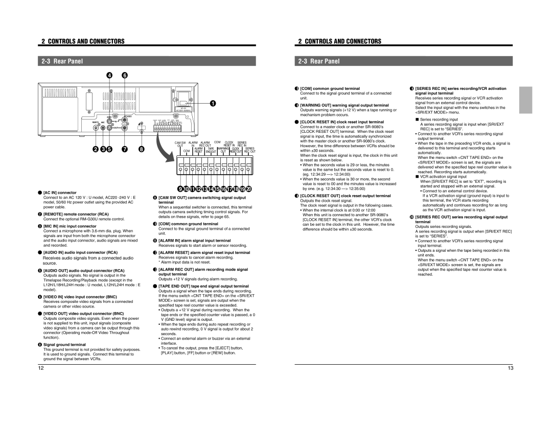
% [COM] common ground terminal Connect to the signal ground terminal of a connected unit.
^ [WARNING OUT] warning signal output terminal Outputs warning signals (+12 V) when a tape running or mechanism problem occurs.
& [CLOCK RESET IN] clock reset input terminal Connect to a master clock or another
( [SERIES REC IN] series recording/VCR activation signal input terminal Receives series recording signal or VCR activation signal from an external control device. Select the input signal with the menu switches in the <SRI/EXT MODE> menu.
5 Series recording input A series recording signal is input when [SRI/EXT REC] is set to “SERIES”. • Connect to another VCR’s series recording signal output terminal.
|
|
|
|
| CAM SW ALARM | ALARM | COM | CLOCK | SERIES | ||||
2 | 3 | 5 | 7 | 8 | OUT | IN | REC OUT |
| RESET IN | REC IN | |||
COM | ALARM | TAPE | WARNING | CLOCK | SERIES | ||||||||
|
|
|
|
| RESET | ENDOUT | OUT | RESET OUT | REC OUT | ||||
However, the time difference between VCRs should be within ±30 seconds. When the clock reset signal is input, the clock in this unit is reset as shown below.
• When the tape in the preceding VCR ends, a signal is delivered to this terminal and recording starts automatically. When the menu switch <CNT TAPE END> on the <SRI/EXT MODE> screen is set, the signals are
1 | [AC IN] connector |
| Connect to an AC 120 V : U model, AC220 |
| model, 50/60 Hz power outlet using the provided AC |
| power cable. |
2 | [REMOTE] remote connector (RCA) |
| Connect the optional |
3 | [MIC IN] mic input connector |
| Connect a microphone with |
| signals are input from both the microphone connector |
| and the audio input connector, audio signals are mixed |
| and recorded. |
4 | [AUDIO IN] audio input connector (RCA) |
| Receives audio signals from a connected audio |
| source. |
5 | [AUDIO OUT] audio output connector (RCA) |
| Outputs audio signals. No signal is output in the |
| Timelapse Recording/Playback mode (except in the |
| L12H/L18H/L24H mode : U model, L12H/L24H mode : E |
| model). |
6 | [VIDEO IN] video input connector (BNC) |
| Receives composite video signals from a connected |
| camera or other video source. |
7 | [VIDEO OUT] video output connector (BNC) |
| Outputs composite video signals. Even when the power |
| is not supplied to this unit, input signals (composite |
| video signals) from a camera can be output through this |
| connector (Operating |
| function). |
8 Signal ground terminal | |
| This ground terminal is not provided for safety purposes. |
| It is used to ground signals. Connect this terminal to |
| ground the signal between VCRs. |
| 9 10 1112 13 1415 16 17 18 19 | 20 |
9 | [CAM SW OUT] camera switching signal output |
|
| terminal |
|
| When a sequential switcher is connected, this terminal | |
| outputs camera switching timing control signals. For | |
| details on these signals, refer to page 65. |
|
0 | [COM] common ground terminal |
|
| Connect to the signal ground terminal of a connected | |
| unit. |
|
! | [ALARM IN] alarm signal input terminal |
|
| Receives signals to start alarm or sensor recording. | |
@ | [ALARM RESET] alarm signal reset input terminal | |
| Receives signals to cancel alarm recording. |
|
| * Alarm input data is not reset. |
|
# | [ALARM REC OUT] alarm recording mode signal | |
| output terminal |
|
| Outputs +12 V signals during alarm recording. |
|
$ | [TAPE END OUT] tape end signal output terminal | |
| Outputs a signal when the tape ends during recording. | |
| If the menu switch <CNT TAPE END> on the <SRI/EXT | |
| MODE> screen is set, signals are output when the |
|
| specified tape reel counter value is exceeded. |
|
| • Outputs a +12 V signal during recording. When the | |
| tape ends or the specified counter value is passed, a 0 | |
| V (GND level) signal is output. |
|
| • When the tape ends during auto repeat recording or | |
| auto rewind recording, 0 V signal is output for about 2 | |
| seconds. |
|
| • Connect an external alarm or buzzer via an external | |
| interface. |
|
| • To cancel the output, press the [EJECT] button, |
|
| [PLAY] button, [FF] button or [REW] button. |
|
•When the seconds value is 29 or less, the minutes value is the same but the seconds value is reset to 0. (eg. 12:34:29
•When the seconds value is 30 or more, the second value is reset to 00 and the minutes value is increased by one. (e.g. 12:34:30
* [CLOCK RESET OUT] clock reset output terminal Outputs the clock reset signal. The clock reset signal is output in the following cases.
•When the internal clock is at 0:00 or 12:00
When this unit is connected to another
delivered when the specified tape reel counter value is reached. Recording starts automatically. 5 VCR activation signal input When [SRI/EXT REC] is set to “EXT”, recording is started and stopped with an external signal. • Connect to an external control device. If a VCR activation signal (ground input) is input to this terminal, the VCR starts recording automatically and continues recording for as long as the VCR activation signal is input.
) [SERIES REC OUT] series recording signal output terminal Outputs series recording signals. A series recording signal is output when [SRI/EXT REC] is set to “SERIES”.
•Connect to another VCR’s series recording signal input terminal.
•Outputs a signal when the tape being recorded in this unit ends.
When the menu switch <CNT TAPE END> on the <SRI/EXT MODE> screen is set, the signals are output when the specified tape reel counter value is reached.
12 | 13 |