3 CONNECTIONS |
| |
|
| |
|
| CCD |
Microphone | Amplifier | Video camera |
|
| |
3 CONNECTIONS
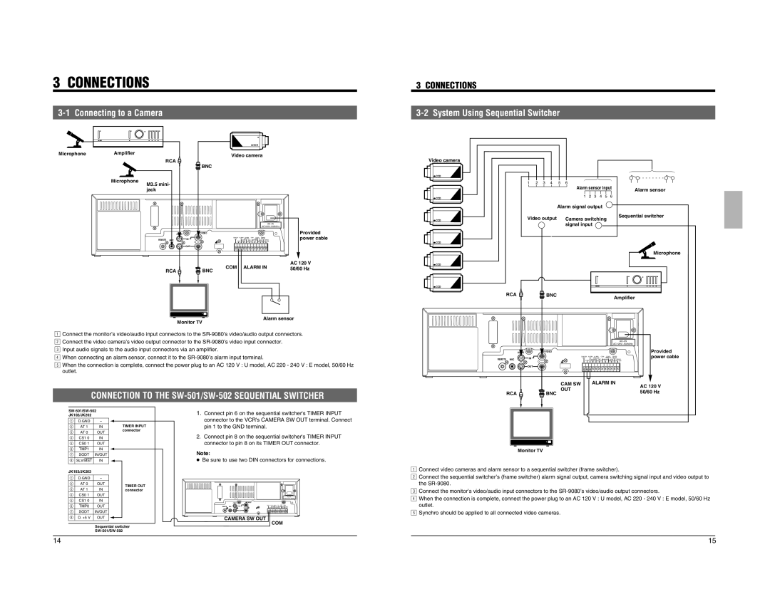
3-2 System Using Sequential Switcher
| RCA |
| BNC |
|
|
|
|
|
|
|
|
|
|
| |
Microphone | M3.5 mini- |
|
|
|
|
|
|
|
|
|
|
|
|
| |
| jack |
|
|
|
|
|
|
| R S - 2 3 2 C |
|
|
|
| AC~IN |
|
|
|
|
|
|
| AC120V~50/60Hz |
|
| AUDIO |
| VIDEO |
|
|
| Provided |
|
| IN | CAM SW ALARM ALARM | COM CLOCK SERIES | power cable | ||
| REMOTE MIC | OUT | IN REC OUT | RESET IN REC IN | |||
|
| ALARM | TAPE WARNING CLOCK SERIES | ||||
|
|
| COM RESET | ENDOUT OUT RESET OUT REC OUT |
| ||
|
| OUT |
|
|
|
|
|
|
|
| COM | ALARM IN | AC 120 V | ||
|
|
| 50/60 Hz | ||||
| RCA |
| BNC |
|
|
| |
|
|
|
|
|
| ||
| Alarm sensor |
1 | Monitor TV |
2Connect the monitor’s video/audio input connectors to the | |
3Connect the video camera’s video output connector to the | |
4Input audio signals to the audio input connectors via an amplifier. | |
5When connecting an alarm sensor, connect it to the | |
| When the connection is complete, connect the power plug to an AC 120 V : U model, AC 220 - 240 V : E model, 50/60 Hz |
| outlet. |
| CONNECTION TO THE |
Video camera
![]() CCD
CCD
![]() CCD
CCD
![]() CCD
CCD
![]() CCD
CCD
![]() CCD
CCD
![]() CCD
CCD
123456 |
| |
| Alarm sensor input | Alarm sensor |
|
| |
| 123456 |
|
| Alarm signal output |
|
Video output | Camera switching | Sequential switcher |
| ||
| signal input |
|
Microphone
RCA | BNC | Amplifier |
|
|
R S - 2 3 2 C |
|
|
|
|
|
|
| AC~IN |
|
|
|
|
|
|
|
| AC120V~50/60Hz |
| |
|
| AUDIO | VIDEO |
|
|
|
|
| Provided |
|
|
| OUT | IN | REC OUT | RESET IN REC IN | power cable | ||
|
| IN | CAM SW ALARM ALARM | COM CLOCK SERIES |
| ||||
REMOTE | MIC | COM |
| ALARM | TAPE WARNING CLOCK | SERIES |
| ||
|
|
| RESET | ENDOUT OUT RESET OUT | REC OUT |
| |||
|
| OUT |
|
|
|
|
|
|
|
|
|
| CAM SW |
| ALARM IN |
| AC 120 V | ||
|
|
| OUT |
|
|
|
|
| |
| RCA |
|
|
|
|
|
| 50/60 Hz | |
|
| BNC |
|
|
|
|
| ||
|
|
|
|
|
|
|
| ||
| ||||||
JK102/JK202 |
|
| ||||
| D.GND |
| – | |||
|
| AT 1 |
| IN | ||
|
| AT 0 |
| OUT | ||
| CS1 0 |
| IN | |||
| CS0 1 |
| OUT | |||
|
|
|
|
|
| IN |
|
| TMP1 |
| |||
| SODT |
| IN/OUT | |||
| SLV/MST |
| IN | |||
|
|
|
|
|
|
|
JK103/JK203 |
|
| ||||
| D.GND |
| – | |||
|
| AT 0 |
| OUT | ||
|
| AT 1 |
| IN | ||
| CS0 1 |
| OUT | |||
| CS1 0 |
| IN | |||
|
|
|
|
|
| OUT |
|
| TMP0 |
| |||
| SODT |
| IN/OUT | |||
| D. +5 V |
| OUT | |||
TIMER INPUT connector
TIMER OUT connector
1. | Connect pin 6 on the sequential switcher's TIMER INPUT |
| connector to the VCR's CAMERA SW OUT terminal. Connect |
| pin 1 to the GND terminal. |
2.Connect pin 8 on the sequential switcher's TIMER INPUT connector to pin 8 on its TIMER OUT connector.
Note:
●Be sure to use two DIN connectors for connections.
AC~IN
AUDIO | VIDEO |
REMOTE MIC | IN |
| OUT |
CAMERA SW OUT
COM
Monitor TV
12Connect video cameras and alarm sensor to a sequential switcher (frame switcher). Connect the sequential switcher’s (frame switcher) alarm signal output, camera switching signal input and video output to 3the
4Connect the monitor’s video/audio input connectors to the
Sequential switcher
14 | 15 |