Connections & Installation
Point-to-Point Communication System
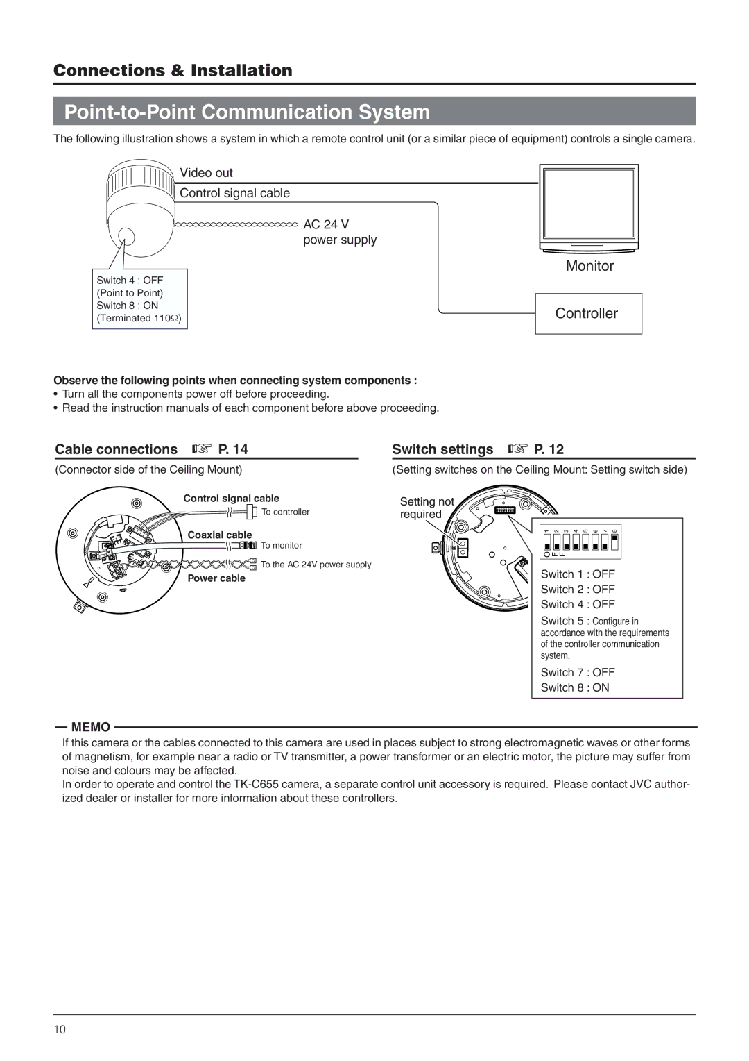
The following illustration shows a system in which a remote control unit (or a similar piece of equipment) controls a single camera.
Video out
Control signal cable
AC 24 V power supply
Switch 4 : OFF (Point to Point) Switch 8 : ON (Terminated 110Ω)
Observe the following points when connecting system components :
•Turn all the components power off before proceeding.
•Read the instruction manuals of each component before above proceeding.
Monitor
Controller
Cable connections ☞ P. 14
(Connector side of the Ceiling Mount)
Control signal cable
To controller
Coaxial cable
To monitor
To the AC 24V power supply
Power cable
Switch settings ☞ P. 12
(Setting switches on the Ceiling Mount: Setting switch side)
Setting not required
1 | 2 | 3 | 4 | 5 | 6 | 7 | 8 |
F
F
O
![]() Switch 1 : OFF
Switch 1 : OFF
![]() Switch 2 : OFF
Switch 2 : OFF
Switch 4 : OFF
Switch 5 : Configure in accordance with the requirements of the controller communication system.
Switch 7 : OFF
Switch 8 : ON
MEMO
If this camera or the cables connected to this camera are used in places subject to strong electromagnetic waves or other forms of magnetism, for example near a radio or TV transmitter, a power transformer or an electric motor, the picture may suffer from noise and colours may be affected.
In order to operate and control the
10