Coaxial cable
Connecting a
If a
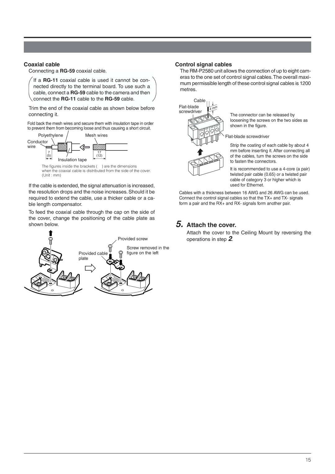
Trim the end of the coaxial cable as shown below before connecting it.
Fold back the mesh wires and secure them with insulation tape in order to prevent them from becoming loose and thus causing a short circuit.
Polyethylene | Mesh wires |
Conductor |
|
wire |
|
7 | 17 |
(5) | (12) |
| Insulation tape |
The figures inside the brackets ( ) are the dimensions
when the coaxial cable is distributed from the side of the cover. (Unit : mm)
If the cable is extended, the signal attenuation is increased, the resolution drops and the noise increases. Should it be required to extend the cable, use a thicker cable or a ca- ble length compensator.
To feed the coaxial cable through the cap on the side of the cover, change the positioning of the cable plate as shown below.
| Provided screw |
| Screw removed in the |
Provided cable | figure on the left |
plate |
|
Control signal cables
The
Cable
screwdriver
The connector can be released by
loosening the screws on the two sides as shown in the figure.
![]()
![]()
Strip the coating of each cable by about 4
mmbefore inserting it. After connecting all of the cables, turn the screws on the side to fasten the connectors.
It is recommended to use a
Cables with a thickness between 16 AWG and 26 AWG can be used. Connect the control signal cables so that the TX+ and TX- signals form a pair and the RX+ and RX- signals form another pair.
5. Attach the cover.
Attach the cover to the Ceiling Mount by reversing the operations in step 2.
15