STEP 3. Attach a
STEP 4. Remove the center terminal block screw. Remove the neutral ground- ing wire (green/yellow wire) from extemal grounding screw.
STEP 5. Connect neutral grounding wire and the neutral wire (white) of power
supply cord under the center screw of terminal block.
STEP 6. Connect the other two insulated wires to outer terminal block screws.
STEP 7. Connect the green, grounding wire from the power supply cord to the external grounding conductor screw.
Tighten all terminal block screws firmly.
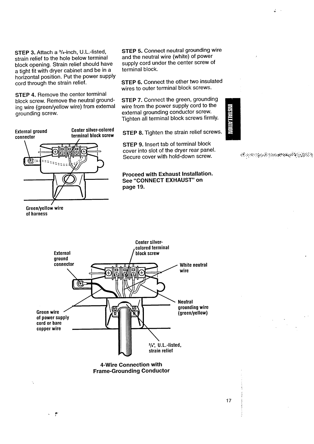
ExternalgroundCentersilver-colored
connectorterminalblockscrew
Green/yellowwire of harness
STEP 8. Tighten the strain relief screws.
STEP 9. Insert tab of terminal block cover into slot of the dryer rear panel. Secure cover with
Proceed with Exhaust Installation. See "CONNECT EXHAUST" on
page 19.
| Centersilver- |
External | coloredterminal |
:k screw | |
ground |
|
connector | White neutral |
| wire |
| Neutral | |
Greenwire | groundingwire | |
(green/yellow) | ||
of powersupply | ||
| ||
cordor bare |
| |
copperwire |
| |
/,, | ||
3 | l! | |
strainrelief | ||
with | ||
17