APPENDIX
VC-H1 DATA PORT PIN FUNCTIONS
Pin No. | Pin Name | Function |
|
|
|
1 | NC | No connection |
|
|
|
2 | SSDO | Image data output (not usually used) |
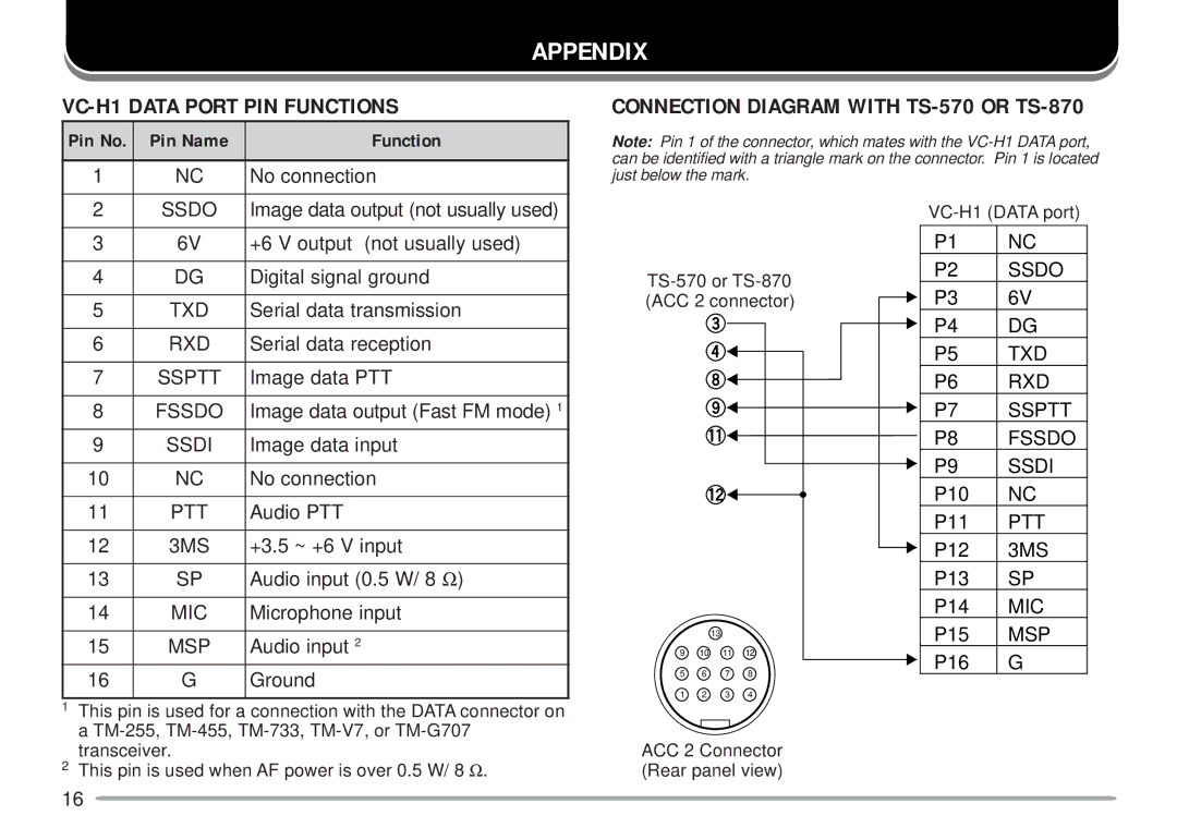
CONNECTION DIAGRAM WITH TS-570 OR TS-870
Note: Pin 1 of the connector, which mates with the
3 | 6V | +6 V output (not usually used) |
4 | DG | Digital signal ground |
|
|
|
5 | TXD | Serial data transmission |
|
|
|
6 | RXD | Serial data reception |
|
|
|
7 | SSPTT | Image data PTT |
|
|
|
8 | FSSDO | Image data output (Fast FM mode) 1 |
|
|
|
9 | SSDI | Image data input |
|
|
|
10 | NC | No connection |
|
|
|
11 | PTT | Audio PTT |
|
|
|
12 | 3MS | +3.5 ~ +6 V input |
|
|
|
13 | SP | Audio input (0.5 W/ 8 Ω) |
|
|
|
14 | MIC | Microphone input |
|
|
|
15 | MSP | Audio input 2 |
16 | G | Ground |
1This pin is used for a connection with the DATA connector on a
2This pin is used when AF power is over 0.5 W/ 8 Ω.
13
9 10 11 12
5 6 7 8
1 2 3 4
ACC 2 Connector (Rear panel view)
P1 | NC |
P2 | SSDO |
P3 | 6V |
P4 | DG |
P5 | TXD |
P6 | RXD |
P7 | SSPTT |
P8 | FSSDO |
P9 | SSDI |
P10 | NC |
P11 | PTT |
P12 | 3MS |
P13 | SP |
P14 | MIC |
P15 | MSP |
P16 | G |
16