Operation Guide
Regarding Tradenames
Symbols
Notice on Software
Notice
3. Limitation of Remedies
2. Limited Warranty
IBM PROGRAM LICENSE AGREEMENT
1. License
9.New York, U.S.A. law governs this Agreement
Contents
Appendix D Option Units
Appendix E Specifications
CONTENTS
Appendix C Host Computer Interface
Item
Introduction
1. For More Information
2. Guide to the Operation Guide
IMPORTANT! PLEASE READ FIRST
Caution Labels
QEnvironment
Installation Precautions
QPower Supply/Grounding the Printer
Other Precautions
QCautions when Using the Printer
Precautions for Use
QCautions for Toner Handling
A B 1 C D E F 2 3 4
Chapter
Names of Parts
M G L K J I H
GPower cord
9Main switch
DCleaning knob
FCleaning brush
Metric specifications
Chapter 2 How to Load Paper
1. How to Load Paper
Inch specifications
1.2Loading Paper into the MP Multi-Pur-pose Tray
Chapter 2 How to Load Paper
1.3 Setting Envelopes
Ready A4 PLAIN
Chapter 3 Using the Operator Panel
1. Understanding the Operator Panel
Message
Chapter 3 Using the Operator Panel
Indicator
DATA
Function
Paper Size
Display
Paper Type
2.1 Menu Selection System
2. Using the Operator Panel
Continued
Continued on the next page
Continued
Print Quality >
Paper Handling >
Life Counters > Others >
STATUS PAGE
2.2.1 Printing the Menu Map
2.2.2 Printing Status Page
3-10
3-11
5Installed Options
8Error Log
2.2.3 e-MPS
e-MPS
>Report
>Private/Stored
>Agenda
>Print VMB Data
e-MPS
2.2.4 Changing the Interface Parameters
>Baud Rate
>Baud Rate >Data Bits >Stop Bits >Parity None
>Protocol DTRpos.&XON >Barcode Mode Off
?Serial
3-20
>>DHCP Off
3-22
Emulation
Emulation
2.2.6 Setting the Default Font
Font
2.2.7 Using Page Set Menus
Page Set
CS→CS98%
Page Set
EcoPrint Mode
2.2.8 Setting the Print Quality
Print Quality >
>KIR Mode
3-31
2.2.9 Operating an Option Hard Disk
>Write Data
Hard Disk
>Read Data
DataH001
Hard Disk
3-34
2.2.10 Operating a RAM Disk
3-35
? DataH001
2.2.11 Operating a Memory Card
Memory Card
Formatting
?DataS001
Memory Card
3-40
6 7 8
Setting the MP Tray Size
2.2.12 Paper Handling
? Plain
Setting the MP Tray Type
>MP Tray Type
Plain
? mm
Setting the Cassette Paper Type
>Cassette1 size
>>Unit
>Cassette 1 Type
Setting Duplex Printing
QBinding Setups
Binding Setups
Paper Handling >
Customizing Paper Type
>Type Adjust > Custom
>Override A4/LT
>Type Adjust
2.2.13 Other Modes
Others
Others
Others
>Buzzer
>>Print Status Page ?
>Service >
Q Printing the Service Status Page
>>Print
See Indicators on page
Chapter 4 Troubleshooting
1. General Guide
Symptom
Replacement on page
2. Print Quality Problems
Chapter 4 Troubleshooting
Clean the charger wire
Check the charger unit installation
Check the EcoPrint setting
Setting the Print Quality on page
Container Replacement on page
Condition
3. Indicators and Messages
READY
a Paper Jam on page
Close the printer front cover
on page
Auto Continue Setting on page
select Auto. See Page Protect Mode on page
correct reading of the memory card
See Memory Card CF on page D-2
Reference Page
4. Correcting a Paper Jam
Paper jam message
Pager jam location
4.2 Jam at the MP Tray
4.1 Jam in Paper Cassette
Close the front cover
8 9 10
4.3 Jam in Left Cover
4-10
4-11
4.4 Jam in Left Cover
4.5 Paper Jam at the Option Document Finisher
Condition of the Paper
Chapter 5 Paper Selection
1. General Guidelines
Specification
MP tray
Basis Weight
Moisture Content
Chapter 5 Paper Selection
Paper type to be used
2. Special Paper
Paper Grain
Other Paper Properties
Recycled Paper
Envelopes
Colored Paper
Preprinted Paper
Duplex path
3. Paper Type
Weight
Paper
1. Toner Container Replacement
Maintenance
cover open to allow insertion of the waste toner
Chapter 6 Maintenance
When inserting, be sure that the gear side of the
plastic bag and dispose of it
16 Remove the blue colored cleaning brush
List of Fonts
Appendix A
Fonts
3PCL Scalable and Bitmap Fonts
Appendix A Fonts
3KPDL Fonts
3KPDL Fonts
1. Removing the Main Circuit Board
Appendix B Expansion Memory
YES NO
Appendix B Expansion Memory
2. Installing DIMMs
2.2 Testing the Expansion Memory
2.1 Removing DIMM
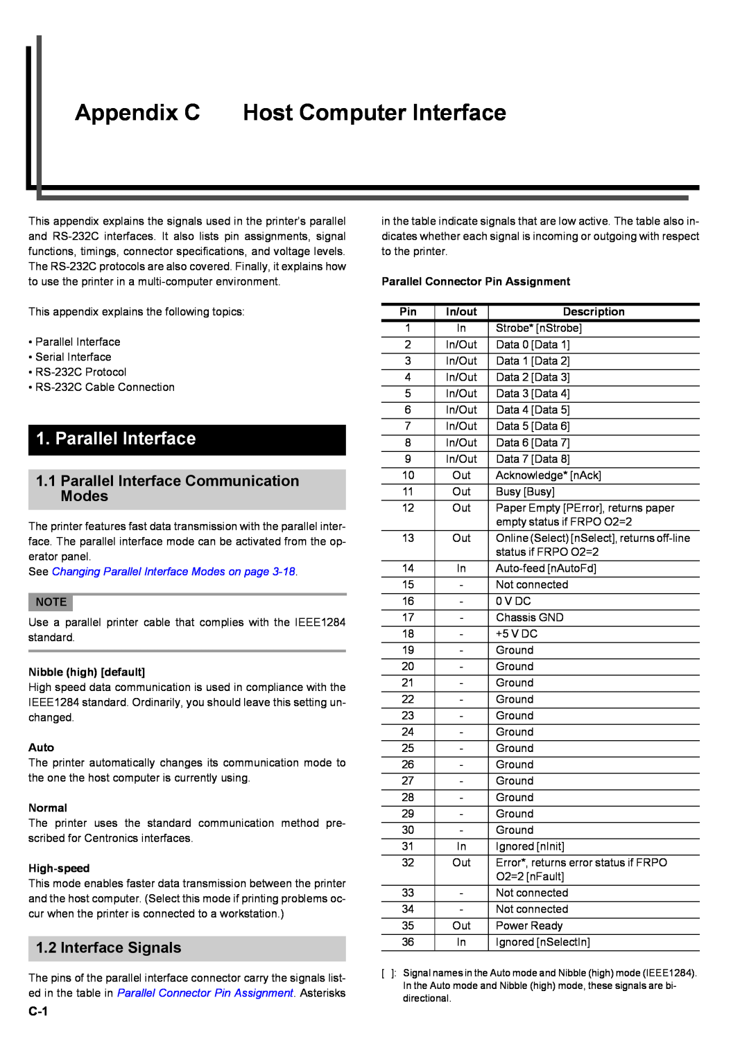
Parallel Connector Pin Assignment
Appendix C Host Computer Interface
1. Parallel Interface
Nibble high default
Error* nFault Pin
2. Serial Interface
Data 0 1 to Data 7 8 Pins 2 to
Paper Empty PError Pin
Error
3. RS-232CProtocol
PRESCRIBE FRPO D0 command
Serial interface error
4.1 Preparing an RS-232CCable
4. RS-232CCable Connection
4.2 Connecting the RS-232CCable
4.3 Setting the RS-232CParameters
QDOS
1. Available Options
Appendix D
Option Units
Network Interface Card
Appendix D Option Units
PF-70Paper Feeder
PF-75Paper Feeder
2.3 Network Interface
2. Installing Option Units
2.1 PF-70/75Paper Feeders
2.2 DF-70/71/75Document Finishers
2.5 Memory Card
2.4 Hard Disk
Specifications
Specifications
Specifications
Appendix E
Appendix E Specifications
dpi dots per inch
Glossary
Glossary-1
Cassette mode
RAM disk
Glossary
Glossary-2
Printer driver
Index
Page
Osaka 540-8585,Japan Phone: 06
Kyocera Mita Corporation
2-28, 1-Chome,Tamatsukuri, Chuo-ku
Printer Driver Guide
Regarding Tradenames
Preface
Notice
Chapter 3 Printing Through Application Software
Chapter 1 Installing the Printer Driver
Chapter 2 Setting the Defaults
9100DN or FS-9500DN
Chapter 1 Installing the Printer Driver
In the Select a device model window, click FS
Chapter 1 Installing the Printer Driver
3 Click the Device Settings tab
Chapter 2 Setting the Defaults
2.1 Adding Option Devices Setup
Browse Start > Settings > Printers
Check Large Capacity Feeder in the Device Options
Chapter 2 Setting the Defaults
Click the Device Settings tab
Check Finisher in the Device Options list box
the Device Options list
2.1.4 Installing the Document Finisher DF-75
Setting the Defaults
Chapter
4 Check RAM Disk in the Device Options list box
4 Check Hard Disk in the Device Options list box
Right click on the Kyocera Mita FS-9100DNKX or
Chapter 2 Setting the Defaults
Browse Start Settings Printers
Click the Device Settings tab
Right click on the Kyocera Mita FS-9100DNKX or
Chapter 2 Setting the Defaults
Browse Start > Settings > Printers
Click the Device Settings tab
Chapter 2 Setting the Defaults
FS-9100DNKX or Kyocera Mita FS-9500DNKX
3.1 Setting the Paper Size
Chapter 3 Printing Through Application Software
Guide
Select Same as Page Size in the Print Size drop
tom Size Settings on page
Chapter 3 Printing Through Application Software
the Customized Paper Sizes list
3.1.1 Custom Size Settings
ters
Transparency Interleaving
3.1.2 Advanced Media Settings
leaving Cover Mode
Page Insert
ing the Booklet Mode on page
3.2 Setting the Duplex Printing
Click Print on Both Sides Duplex and then check
the Flip on Long Edge or Flip on Short Edge radio
Select Finisher Face-down as Output to
3.3 Using the Booklet Mode
1 2 3
Finishing Options
3.4Using the Document Finisher DF-70/DF-71
Collate box
Select Finisher Face-down or Finisher Face-up
Face-down or Finisher Face-up.To use the staple
3.5 Using the Document Finisher
DF-75
document, All or Current page only in Page range
Virtual MailBox
3.6 e-MPS
Job Retention
Quick Copy Printing
Job Settings button
Code Job Temporary and Parmanent
Proof and Hold Printing
Private Printing
Proof and Hold
Job Storage Stored Job Printing
Job Storage
Select PCL XL or PCL 5e in the Page Description
3Before Using VMB
1 Browse Start > Settings > Printers
3 Select the Device Settings tab
3Using VMB Printing
Virtual Mail Box VMB
porary or Permanent radio button
Settings button
Lower left
horizontal
vertical
Upper left
Osaka 540-8585,Japan Phone: 06
Kyocera Mita Corporation
2-28, 1-Chome,Tamatsukuri, Chuo-ku