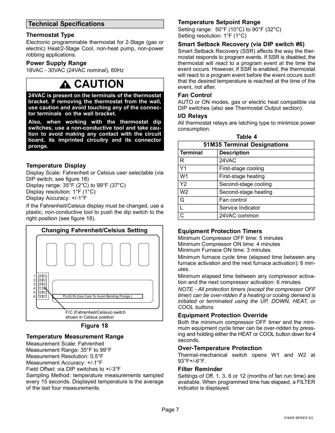
51M37 specifications
Lennox International Inc, a prominent player in the heating, ventilation, and air conditioning (HVAC) market, has made significant strides in innovation and technology in recent years. Among its notable offerings is the Lennox 51M37, a well-engineered component designed to enhance HVAC efficiency and reliability.The 51M37 is primarily known for its advanced motor technology, incorporating ECM (Electronically Commutated Motor) design, which significantly reduces energy consumption compared to traditional motor systems. This motor type is key to Lennox's commitment to sustainability, as it not only maintains optimal performance but also minimizes the carbon footprint associated with residential and commercial heating and cooling tasks.
A standout feature of the 51M37 is its intelligent control system, which allows for more precise management of airflow and temperature. This technology can adapt to specific environmental conditions and consumption patterns, optimizing performance and providing substantial cost savings on energy bills. The integration of smart technology aligns with modern demands for energy efficiency and control, making the 51M37 a vital component in achieving higher energy ratings for HVAC systems.
In terms of compatibility, the 51M37 is engineered to work seamlessly with a variety of Lennox heating and cooling units, ensuring versatility for both new installations and retrofits. This compatibility enhances system integration, resulting in improved overall performance.
The construction of the 51M37 emphasizes durability and reliability, featuring high-quality materials that withstand the challenges of constant operation. Its robust design is perfect for diverse environments, ensuring that it functions reliably in both residential settings and commercial applications.
Another characteristic worth noting is the user-friendly installation process, allowing HVAC technicians to install the 51M37 with relative ease. This not only reduces labor costs but also ensures that the system can commence operation quickly without extensive downtime.
Overall, Lennox International's 51M37 embodies innovation, efficiency, and reliability in HVAC technology. With its advanced ECM motor, intelligent controls, and durable construction, it stands as a prime example of how modern HVAC solutions can lead to enhanced performance and energy savings. As the industry continues to evolve, products like the 51M37 will play a critical role in shaping the future of heating and cooling, aligning with sustainability goals and meeting the needs of consumers.

