![]() WARNING
WARNING
Improper installation of the furnace can result in per sonal injury or death. Combustion and flue products must never be allowed to enter the return air system or air in the living space. Use sheet metal screws and joint tape to seal return air system to furnace.
In platform installations with furnace return, the fur nace should be sealed airtight to the return air ple num. A door must never be used as a portion of the return air duct system. The base must provide a stable support and an airtight seal to the furnace. Al low absolutely no sagging, cracks, gaps, etc.
For no reason should return and supply air duct sys tems ever be connected to or from other heating de vices such as a fireplace or stove, etc. Fire, explo sion, carbon monoxide poisoning, personal injury and/or property damage could result.
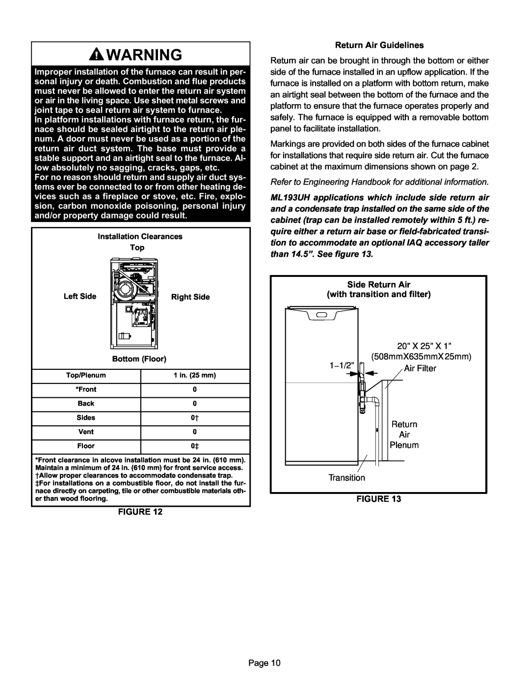
| Installation Clearances |
| Top |
Left Side | Right Side |
Bottom (Floor)
Top/Plenum | 1 in. (25 mm) |
|
|
*Front | 0 |
|
|
Back | 0 |
|
|
Sides | 0† |
|
|
Vent | 0 |
|
|
Floor | 0‡ |
|
|
*Front clearance in alcove installation must be 24 in. (610 mm). Maintain a minimum of 24 in. (610 mm) for front service access.
†Allow proper clearances to accommodate condensate trap.
‡For installations on a combustible floor, do not install the fur nace directly on carpeting, tile or other combustible materials oth er than wood flooring.
FIGURE 12
Return Air Guidelines
Return air can be brought in through the bottom or either side of the furnace installed in an upflow application. If the furnace is installed on a platform with bottom return, make an airtight seal between the bottom of the furnace and the platform to ensure that the furnace operates properly and safely. The furnace is equipped with a removable bottom panel to facilitate installation.
Markings are provided on both sides of the furnace cabinet for installations that require side return air. Cut the furnace cabinet at the maximum dimensions shown on page 2.
Refer to Engineering Handbook for additional information.
ML193UH applications which include side return air and a condensate trap installed on the same side of the cabinet (trap can be installed remotely within 5 ft.) re quire either a return air base or
Side Return Air
(with transition and filter)
20” X 25” X 1” (508mmX635mmX25mm)
1−1/2” | Air Filter |
|
Return
Air
Plenum
Transition
FIGURE 13
Page 10