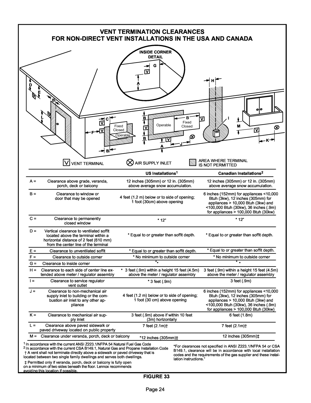
VENT TERMINATION CLEARANCES
FOR
INSIDE CORNER
DETAIL
|
|
| G |
|
|
|
| A |
|
| H |
D |
|
|
|
| |
|
|
|
|
| |
E |
|
|
|
|
|
| B |
|
|
|
|
L | C | B |
| B | I |
|
|
| Fixed |
| |
|
|
| Operable |
| |
|
| Fixed | Closed | M | |
|
|
| |||
| F | Closed |
|
|
|
| Operable |
|
|
| |
|
|
|
|
| |
|
| B |
|
| K |
|
|
|
| J | |
|
|
| A |
| |
|
|
|
|
| |
| B |
|
|
|
|
VENT TERMINAL | AIR SUPPLY INLET |
AREA WHERE TERMINAL IS NOT PERMITTED
|
|
|
|
| US Installations1 | Canadian Installations2 |
| |||
|
| A = | Clearance above grade, veranda, | 12 inches (305mm) or 12 in. (305mm) | 12 inches (305mm) or 12 in. (305mm) | |||||
|
|
| porch, deck or balcony | above average snow accumulation. | above average snow accumulation. | |||||
|
|
|
|
|
|
|
|
|
| |
|
| B = | Clearance to window or | 4 feet (1.2 m) below or to side of opening; | 6 inches (152mm) for appliances <10,000 | |||||
|
|
| door that may be opened | Btuh (3kw), 12 inches (305mm) for | ||||||
|
|
|
| 1 foot (30cm) above opening | ||||||
|
|
|
|
| appliances > 10,000 Btuh (3kw) and | |||||
|
|
|
|
|
| |||||
|
|
|
|
|
| <100,000 Btuh (30kw), 36 inches (.9m) | ||||
|
|
|
|
|
| for appliances > 100,000 Btuh (30kw) | ||||
|
|
|
|
|
|
|
|
|
|
|
|
| C = | Clearance to permanently |
| * 12” | * 12” | ||||
|
|
| closed window |
| ||||||
|
|
|
|
|
|
|
|
|
| |
|
|
|
|
|
|
|
|
|
|
|
|
| D = | Vertical clearance to ventilated soffit |
|
|
|
|
|
|
|
|
|
| located above the terminal within a | * Equal to or greater than soffit depth. | * Equal to or greater than soffit depth. | |||||
|
|
| horizontal distance of 2 feet (610 mm) |
|
|
|
|
|
|
|
|
|
| from the center line of the terminal |
|
|
|
|
|
|
|
|
| E = | Clearance to unventilated soffit | * Equal to or greater than soffit depth. | * Equal to or greater than soffit depth. |
| ||||
|
| F = | Clearance to outside corner |
| * No minimum to outside corner | * No minimum to outside corner | ||||
|
|
|
|
|
|
|
|
|
| |
|
| G = Clearance to inside corner |
| ** | * * |
|
|
|
| |
|
| H = Clearance to each side of center line ex | * 3 feet (.9m) within a height 15 feet (4.5m) | 3 feet (.9m) within a height 15 feet (4.5m) | ||||||
|
|
| tended above meter / regulator assembly | above the meter / regulator assembly | above the meter / regulator assembly | |||||
|
|
|
|
|
|
|
|
|
| |
|
| I = | Clearance to service regulator |
| * 3 feet (.9m) | 3 feet (.9m) | ||||
|
|
| vent outlet |
|
|
|
|
|
|
|
|
| J = | Clearance to |
|
| 6 inches (152mm) for appliances <10,000 | ||||
|
|
| supply inlet to building or the com | 4 feet (1.2 m) below or to side of opening; | Btuh (3kw), 12 inches (305mm) for | |||||
|
|
| bustion air inlet to any other ap |
| 1 foot (30 cm) above opening | appliances > 10,000 Btuh (3kw) and | ||||
|
|
| pliance |
|
| <100,000 Btuh (30kw), 36 inches (.9m) | ||||
|
|
|
|
|
| for appliances > 100,000 Btuh (30kw) |
| |||
|
| K = | Clearance to mechanical air sup |
| 3 feet (.9m) above if within 10 feet | 6 feet (1.8m) | ||||
|
|
| ply inlet |
| (3m) horizontally |
|
|
|
|
|
|
| L = | Clearance above paved sidewalk or |
| 7 feet (2.1m)† | 7 feet (2.1m)† | ||||
|
|
| paved driveway located on public property |
|
|
|
|
|
|
|
|
|
|
|
|
|
| ||||
|
| M = Clearance under veranda, porch, deck or balcony | *12 inches (305mm)‡ | 12 inches (305mm)‡ | ||||||
|
|
|
|
|
|
|
|
|
| |
1In accordance with the current ANSI Z223.1/NFPA 54 Natural Fuel Gas Code
2In accordance with the current CSA B149.1, Natural Gas and Propane Installation Code
†A vent shall not terminate directly above a sidewalk or paved driveway that is
located between two single family dwellings and serves both dwellings.
‡Permitted only if veranda, porch, deck or balcony is fully open on a minimum of two sides beneath the floor. Lennox recommends avoiding this location if possible.
*For clearances not specified in ANSI Z223.1/NFPA 54 or CSA B149.1, clearance will be in accordance with local installation codes and the requirements of the gas supplier and these instal lation instructions.”
FIGURE 33
Page 24