Electrical
ELECTROSTATIC DISCHARGE (ESD)
Precautions and Procedures
![]() CAUTION
CAUTION
Electrostatic discharge can affect elec tronic components. Take precautions to neutralize electrostatic charge by touching your hand and tools to metal prior to handling the control.
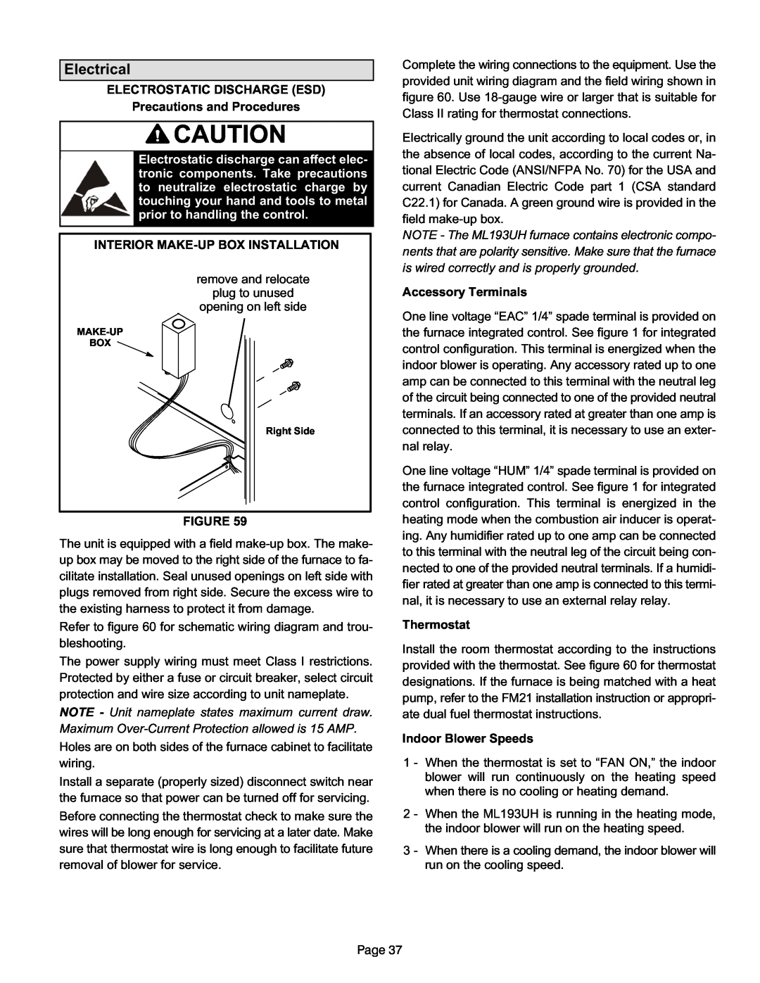
INTERIOR MAKE-UP BOX INSTALLATION
remove and relocate
plug to unused
opening on left side
BOX
Right Side
FIGURE 59
The unit is equipped with a field
Refer to figure 60 for schematic wiring diagram and trou bleshooting.
The power supply wiring must meet Class I restrictions. Protected by either a fuse or circuit breaker, select circuit protection and wire size according to unit nameplate.
NOTE - Unit nameplate states maximum current draw. Maximum
Holes are on both sides of the furnace cabinet to facilitate wiring.
Install a separate (properly sized) disconnect switch near the furnace so that power can be turned off for servicing.
Before connecting the thermostat check to make sure the wires will be long enough for servicing at a later date. Make sure that thermostat wire is long enough to facilitate future removal of blower for service.
Complete the wiring connections to the equipment. Use the provided unit wiring diagram and the field wiring shown in figure 60. Use
Electrically ground the unit according to local codes or, in the absence of local codes, according to the current Na tional Electric Code (ANSI/NFPA No. 70) for the USA and current Canadian Electric Code part 1 (CSA standard C22.1) for Canada. A green ground wire is provided in the field
NOTE - The ML193UH furnace contains electronic compo nents that are polarity sensitive. Make sure that the furnace is wired correctly and is properly grounded.
Accessory Terminals
One line voltage “EAC” 1/4” spade terminal is provided on the furnace integrated control. See figure 1 for integrated control configuration. This terminal is energized when the indoor blower is operating. Any accessory rated up to one amp can be connected to this terminal with the neutral leg of the circuit being connected to one of the provided neutral terminals. If an accessory rated at greater than one amp is connected to this terminal, it is necessary to use an exter nal relay.
One line voltage “HUM” 1/4” spade terminal is provided on the furnace integrated control. See figure 1 for integrated control configuration. This terminal is energized in the heating mode when the combustion air inducer is operat ing. Any humidifier rated up to one amp can be connected to this terminal with the neutral leg of the circuit being con nected to one of the provided neutral terminals. If a humidi fier rated at greater than one amp is connected to this termi nal, it is necessary to use an external relay relay.
Thermostat
Install the room thermostat according to the instructions provided with the thermostat. See figure 60 for thermostat designations. If the furnace is being matched with a heat pump, refer to the FM21 installation instruction or appropri ate dual fuel thermostat instructions.
Indoor Blower Speeds
1 - When the thermostat is set to “FAN ON,” the indoor blower will run continuously on the heating speed when there is no cooling or heating demand.
2 - When the ML193UH is running in the heating mode, the indoor blower will run on the heating speed.
3 - When there is a cooling demand, the indoor blower will run on the cooling speed.
Page 37