NOTE - Assembly should be completed within 20 sec onds after last application of cement. Hammer blows should not be used when inserting pipe.
8 - After assembly, wipe excess cement from pipe at end of fitting socket. A properly made joint will show a bead around its entire perimeter. Any gaps may indicate an improper assembly due to insufficient solvent.
9 - Handle joints carefully until completely set.
Venting Practices
Piping Suspension Guidelines
SCHEDULE 40
PVC - 5'
all other pipe* - 3'
* See table 2 for allowable pipe.
NOTE - Isolate piping at the point where it exits the outside wall or roof in order to prevent transmission of vibration to the structure.
Wall Thickness Guidelines
24” maximum 3/4” minimum
inside |
|
| Wall outside | ||||||||
|
|
|
|
|
|
|
|
|
|
|
|
|
|
|
|
|
|
|
|
|
|
|
|
|
|
|
|
|
|
|
|
|
|
|
|
FIGURE 20
1 - In areas where piping penetrates joists or interior walls, hole must be large enough to allow clearance on all sides of pipe through center of hole using a hanger.
2 - When furnace is installed in a residence where unit is shut down for an extended period of time, such as a vacation home, make provisions for draining conden sate collection trap and lines.
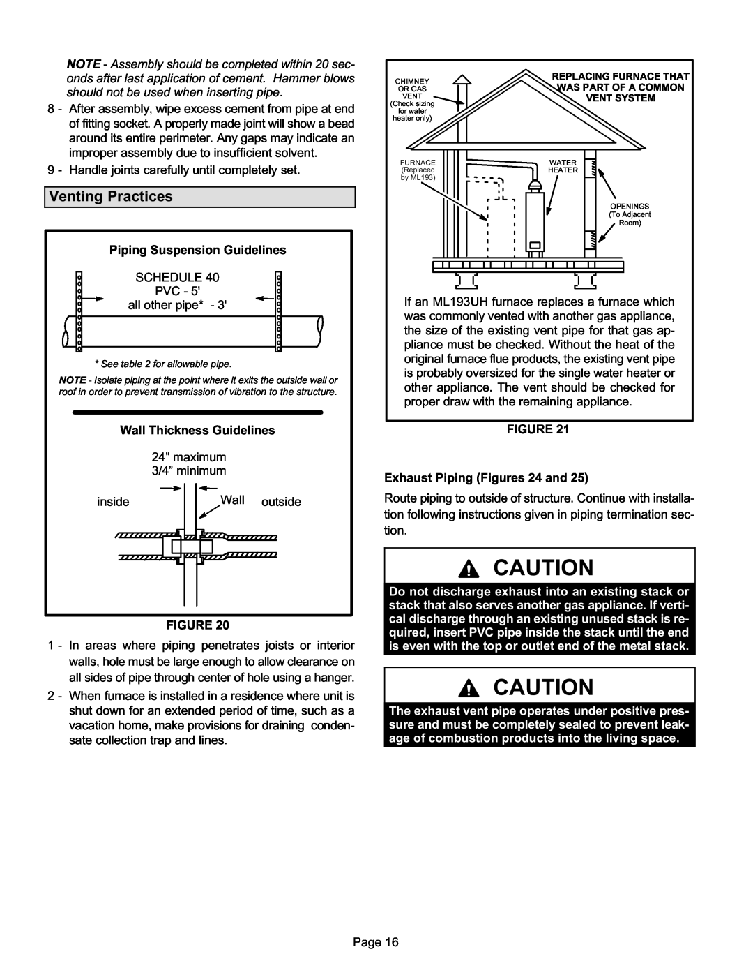
CHIMNEY |
| REPLACING FURNACE THAT |
OR GAS |
| WAS PART OF A COMMON |
VENT |
| VENT SYSTEM |
(Check sizing |
|
|
for water |
|
|
heater only) |
|
|
|
| |
|
|
|
FURNACE | WATER |
(Replaced | HEATER |
by ML193) |
|
| OPENINGS |
| (To Adjacent |
| Room) |
If an ML193UH furnace replaces a furnace which was commonly vented with another gas appliance, the size of the existing vent pipe for that gas ap pliance must be checked. Without the heat of the original furnace flue products, the existing vent pipe is probably oversized for the single water heater or other appliance. The vent should be checked for proper draw with the remaining appliance.
FIGURE 21
Exhaust Piping (Figures 24 and 25)
Route piping to outside of structure. Continue with installa tion following instructions given in piping termination sec tion.
CAUTION
Do not discharge exhaust into an existing stack or stack that also serves another gas appliance. If verti cal discharge through an existing unused stack is re quired, insert PVC pipe inside the stack until the end is even with the top or outlet end of the metal stack.
CAUTION
The exhaust vent pipe operates under positive pres sure and must be completely sealed to prevent leak age of combustion products into the living space.
Page 16