Air from Outside
If air from outside is brought in for combustion and ventila tion, the confined space shall be provided with two perma nent openings. One opening shall be within 12” (305mm) of the top of the enclosure and one within 12” (305mm) of the bottom. These openings must communicate directly or by ducts with the outdoors or spaces (crawl or attic) that freely communicate with the outdoors or indirectly through verti cal ducts. Each opening shall have a minimum free area of 1 square inch per 4,000 Btu (645mm2 per 1.17kW) per hour of total input rating of all equipment in the enclosure. When communicating with the outdoors through horizontal ducts, each opening shall have a minimum free area of 1 square inch per 2,000 Btu (645mm2 per .59kW) per total input rat ing of all equipment in the enclosure (See figure 5). It is also permissible to bring in air for combustion from a ventilated attic (figure 6) or ventilated crawl space (figure 7).
EQUIPMENT IN CONFINED SPACE - ALL AIR FROM OUTSIDE
(Inlet Air from Crawl Space and Outlet Air to Ouside)
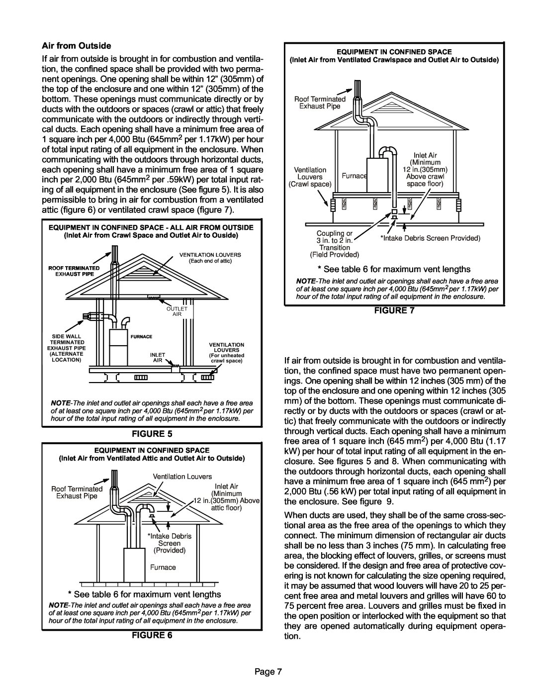
EQUIPMENT IN CONFINED SPACE
(Inlet Air from Ventilated Crawlspace and Outlet Air to Outside)
Roof Terminated
Exhaust Pipe
|
|
|
|
|
|
|
|
|
|
|
|
|
|
|
|
|
|
|
|
|
|
|
|
| Inlet Air |
|
|
| ||
|
|
|
|
|
|
|
|
|
|
|
|
|
|
|
|
|
|
|
|
|
|
|
|
|
|
|
| |||
|
|
|
|
|
|
|
|
|
|
|
|
|
|
|
|
|
|
|
|
|
|
|
|
|
|
|
| |||
|
|
|
|
|
|
|
|
|
|
|
|
|
|
|
|
|
|
|
|
|
|
|
|
|
|
|
| |||
|
|
|
|
|
|
|
|
|
|
|
|
|
|
|
|
|
|
|
|
|
|
|
|
|
|
|
| |||
|
|
|
|
|
|
|
|
|
|
|
|
|
|
|
|
|
|
|
|
|
|
|
| (Minimum |
|
|
| |||
Ventilation |
| Furnace |
|
|
|
|
|
|
|
|
|
|
|
| 12 in.(305mm) |
|
|
| ||||||||||||
Louvers |
|
|
|
|
|
|
|
|
|
|
|
|
|
| Above crawl |
|
|
| ||||||||||||
(Crawl space) |
|
|
|
|
|
|
|
|
|
|
|
|
|
|
|
|
|
|
| space floor) |
|
|
| |||||||
|
|
|
|
|
|
|
|
|
|
|
|
|
|
|
|
|
|
|
|
|
|
|
|
|
|
|
|
|
|
|
|
|
|
|
|
|
|
|
|
|
|
|
|
|
|
|
|
|
|
|
|
|
|
|
|
|
|
|
|
|
|
|
|
|
|
|
|
|
|
|
|
|
|
|
|
|
|
|
|
|
|
|
|
|
|
|
|
|
|
|
|
|
|
|
|
|
|
|
|
|
|
|
|
|
|
|
|
|
|
|
|
|
|
|
|
|
|
|
|
|
|
|
|
|
|
|
|
|
|
|
|
|
|
|
|
|
|
|
|
|
|
|
|
|
|
|
|
|
|
|
|
|
|
|
|
|
|
|
|
|
|
|
|
|
|
|
|
|
|
|
|
|
|
|
|
|
|
|
|
|
|
|
|
|
|
|
|
|
|
|
|
|
|
|
|
|
|
|
|
|
|
|
|
|
|
|
|
|
|
|
|
|
|
|
|
|
Coupling or
3 in. to 2 in. *Intake Debris Screen Provided)
Transition
ROOF TERMINATED EXHAUST PIPE
SIDE WALL
TERMINATED EXHAUST PIPE (ALTERNATE LOCATION)
VENTILATION LOUVERS
(Each end of attic)
OUTLET
AIR
FURNACE
| VENTILATION |
| LOUVERS |
INLET | (For unheated |
AIR | crawl space) |
(Field Provided)
* See table 6 for maximum vent lengths
FIGURE 7
If air from outside is brought in for combustion and ventila tion, the confined space must have two permanent open ings. One opening shall be within 12 inches (305 mm) of the top of the enclosure and one opening within 12 inches (305
FIGURE 5
EQUIPMENT IN CONFINED SPACE
(Inlet Air from Ventilated Attic and Outlet Air to Outside)
mm) of the bottom. These openings must communicate di |
rectly or by ducts with the outdoors or spaces (crawl or at |
tic) that freely communicate with the outdoors or indirectly |
through vertical ducts. Each opening shall have a minimum |
free area of 1 square inch (645 mm2) per 4,000 Btu (1.17 |
kW) per hour of total input rating of all equipment in the en |
closure. See figures 5 and 8. When communicating with |
the outdoors through horizontal ducts, each opening shall |
Roof Terminated
Exhaust Pipe
Ventilation Louvers
Inlet Air
(Minimum
12 in.(305mm) Above
attic floor)
*Intake Debris
Screen
(Provided)
have a minimum free area of 1 square inch (645 mm2) per |
2,000 Btu (.56 kW) per total input rating of all equipment in |
the enclosure. See figure 9. |
When ducts are used, they shall be of the same
Furnace
* See table 6 for maximum vent lengths
FIGURE 6
be considered. If the design and free area of protective cov ering is not known for calculating the size opening required, it may be assumed that wood louvers will have 20 to 25 per cent free area and metal louvers and grilles will have 60 to 75 percent free area. Louvers and grilles must be fixed in the open position or interlocked with the equipment so that they are opened automatically during equipment opera tion.
Page 7