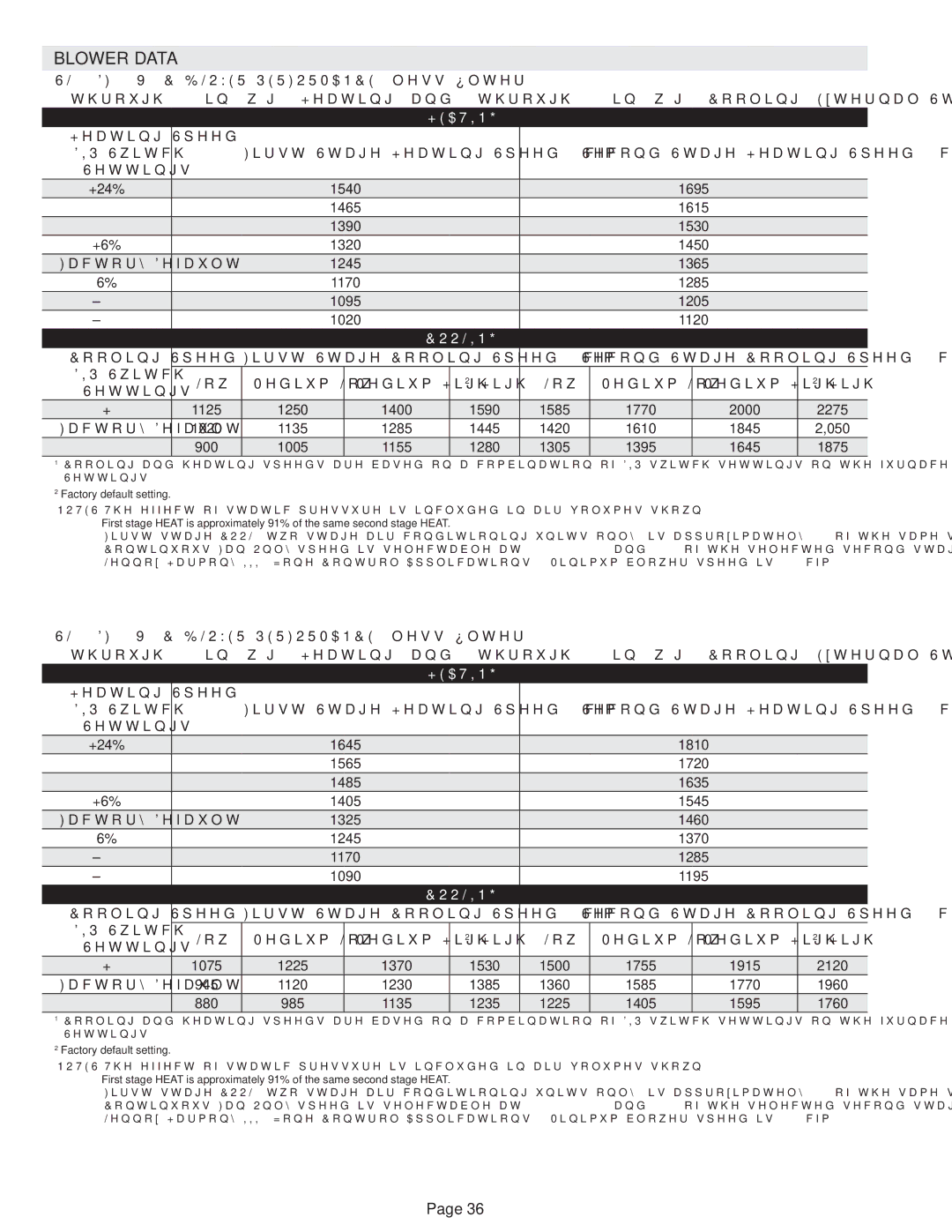
DAVE LENNOX SIGNATURE COLLECTION GAS FURNACE, SL280DFV specifications
Lennox International Inc has made a significant mark in the heating, ventilation, and air conditioning (HVAC) industry, known for its commitment to innovation and energy efficiency. One of its standout products is the SL280DFV model, a high-efficiency gas furnace designed to meet the needs of modern homes.The SL280DFV boasts an impressive Annual Fuel Utilization Efficiency (AFUE) rating of up to 80%. This rating indicates that the furnace converts 80% of the fuel it consumes into usable heat, making it a cost-effective choice for homeowners. The high efficiency not only reduces energy bills but also lessens the environmental impact by minimizing greenhouse gas emissions.
One of the key features of the SL280DFV is its two-stage gas valve operation. This technology allows the furnace to operate at two levels of heating output: low stage for milder days and high stage for extremely cold temperatures. This adaptability enhances comfort by maintaining more consistent indoor temperatures while also saving energy when full power is unnecessary.
Another innovative aspect of the SL280DFV is its variable-speed blower motor. This smart technology enables the furnace to adjust airflow based on the heating needs of a home, which promotes quiet operation and improved temperature consistency throughout living spaces.
The SL280DFV is equipped with a durable heat exchanger that is designed to withstand the rigors of daily use, contributing to the unit’s longevity. Additionally, the furnace features a smart ignition system that ensures reliable start-ups, so homeowners can depend on it through the coldest winter nights.
Safety is also a priority in the design of the SL280DFV. It includes various safety features such as a built-in flame sensor and advanced venting system, designed to avert hazardous situations and ensure optimal operation.
Furthermore, Lennox offers convenient installation and maintenance support, making the SL280DFV not only an efficient heating solution but also a practical choice for homeowners. With its blend of advanced technology, high efficiency, and reliability, the Lennox SL280DFV is an appealing option for those looking to upgrade their home’s heating system, promising comfort and peace of mind for many winters to come.

