Hardware Maintenance Manual
Page
Hardware Maintenance Manual
Page
Contents
FRU lists 135
Acpi Bios
About this manual
Important Safety Information
FRU Identification for CTO, CMV, and GAV products
Dynamic Configure To Order CTO
Important information about replacing RoHS compliant FRUs
Using eSupport
Related Web URLs are
Electrical safety
General safety
Hardware Maintenance Manual
Safety inspection guide
Grounding requirements
Handling electrostatic discharge-sensitive devices
To Connect To Disconnect
Safety notices multi-lingual translations
Do not
Safety information
Hardware Maintenance Manual
Safety information
≥18 kg 37 lbs ≥32 kg 70.5 lbs ≥55 kg 121.2 lbs
Para Conectar Para Desconectar
Perigo
Cuidado
Cuidado
Hardware Maintenance Manual
Safety information
Hardware Maintenance Manual
Safety information
Hardware Maintenance Manual
Connexion Déconnexion
Ne pas
≥18 kg 37 lbs ≥32 kg 70.5 lbs ≥55 kg 121.2 lbs
Vorsicht
Achtung
Arbeitsschutzrichtlinien beim Anheben der Maschine beachten
Safety information
Hardware Maintenance Manual
Safety information
Per collegarsi Per scollegarsi
Pericolo
Attenzione
Prestare attenzione nel sollevare l’apparecchiatura
Safety information
Hardware Maintenance Manual
Safety information
Peligro
No debe
Adopte procedimientos seguros al levantar el equipo
Access IBM program
Physical specifications
Additional information resources
Types 8126, 8174, 8175,
Types 8149, 8177,
Types 8084, 8085, 8147, 8148,
General Checkout
Select Start Options Set Power-On Self-Test to Enhanced
Problem determination tips
Green Yellow Power LED Diagnostic LED Action
OFF
General Checkout
Hardware Maintenance Manual
Starting PC-Doctor from the Rescue and Recovery workspace
Diagnostics using PC-Doctor for DOS
Diagnostics program download
Starting PC-Doctor from a diagnostic diskette or CD-ROM
Navigating through the diagnostics programs
Running diagnostics tests
Test selection
Test results
Fixed disk advanced test Fdat
Fixed-Disk Tests
Quick and Full erase hard drive
Destructive versus non-destructive testing
Viewing the test log
Viewing and changing settings
Starting the Setup Utility program
Exiting from the Setup Utility program
Using passwords
User Password
Password considerations
Administrator Password
IDE Drive User Password
Using Security Profile by Device
Setting, changing, and deleting a password
Diskette Drive Access
IDE controller
Selecting a startup device
Advanced settings
Selecting a temporary startup device
Changing the startup device sequence
Power Supply Errors
Hard disk drive boot error
Error FRU/Action
Check/Verify FRU/Action
Make sure the power cord is attached to a working
Diagnostic error codes
Hardware Maintenance Manual
001-034-XXX Reboot the system
Diagnostic Error Code FRU/Action 001-027-XXX Run Setup
001-039-XXX Flash the system. See Flash update
001-040-XXX Power-off/on system and re-test
Hardware Maintenance Manual
Symptom-to-FRU Index
005-032-XXX Video card, if installed
Diagnostic Error Code FRU/Action 005-031-XXX Video cable
005-036-XXX Video card, if installed
005-038-XXX Video card, if installed
011-027-XXX Run Setup, enable port
It is connected and/or enabled
006-196-XXX Press F3 to review the log file
006-197-XXX If a component is called out, make sure
011-196-XXX Press F3 to review the log file
014-027-XXX Run Setup, enable port
011-197-XXX Make sure the component that is called
011-198-XXX If a component is called out, make sure
014-195-XXX Information only
015-027-XXX Flash the system. See Flash update
014-196-XXX Press F3 to review the log file
014-197-XXX Make sure the component that is called
018-0XX-XXX Riser card, if installed
015-040-XXX Run setup and check for conflicts
015-035-XXX Remove USB devices and re-test
015-036-XXX System board
018-198-XXX If a component is called out, make sure
018-197-XXX Make sure the component that is called
018-199-XXX
018-250-XXX PCI card
025-027-XXX IDE signal cable
025-00X-XXX IDE signal cable 025-01X-XXX
025-02X-XXX IDE signal cable 025-03X-XXX
020-199-XXX
030-027-XXX Scsi signal cable
030-00X-XXX Scsi signal cable 030-01X-XXX
030-03X-XXX Scsi signal cable 030-04X-XXX
025-199-XXX
030-199-XXX
035-0XX-XXX RAID signal cable
035-000-XXX No action
035-195-XXX Information only
071-02X-XXX
071-04X-XXX Run Setup
071-03X-XXX Speakers
071-195-XXX Information only
080-197-XXX Make sure the component that is called
086-040-XXX Run Setup
080-198-XXX If a component is called out, make sure
080-199-XXX
086-198-XXX If a component is called out, make sure
089-198-XXX Flash the system. See Flash update
086-199-XXX
089-000-XXX No action
170-199-XXX See Undetermined problems on
Diagnostic Error Code FRU/Action 170-0XX-XXX Flash system
170-250-XXX Power supply 170-251-XXX
170-195-XXX Information only
185-278-XXX Assure Asset Security Enabled
175-199-XXX See Undetermined problems on
175-198-XXX If a component is called out, make sure
175-250-XXX Check fans 175-251-XXX
Check power supply voltages
CD-ROM Drive error
Hi-Capacity Cartridge Drive error
Keyboard error
Remove the Modem and re-test the system
Modem error
Beeps Description
Beep symptoms
Symptom-to-FRU Index
Symptom/Error FRU/Action
No-beep symptoms
Post error codes
201
Post Error Code FRU/Action
210
211
5962
1962
Miscellaneous error messages
If network administrator is using
See Power Supply Errors on
Display
Printer
Undetermined problems
Replacing FRUs Types 8126, 8174, 8175,
Locating connectors on the front
Removing the cover
Locating the connectors on the rear
Replacing FRUs Types 8126, 8174, 8175, and 8176
Locating components
Identifying parts on the system board
Removing and replacing a PCI adapter
Removing and replacing memory
Removing and replacing the battery
Removing and replacing the power supply
Removing and replacing the microprocessor
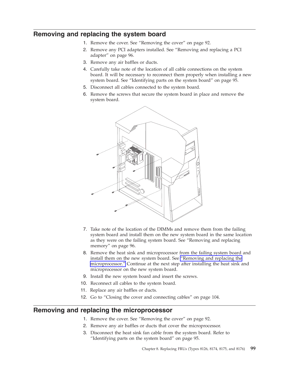
Removing and replacing the system board
Hardware Maintenance Manual
Removing and replacing drives
Hardware Maintenance Manual
Replacing FRUs Types 8126, 8174, 8175, and 8176
Closing the cover and connecting cables
Replacing FRUs Types 8149, 8177,
Locating connectors on the rear
CD drive or DVD drive �7� DIMMs
Identifying parts on the system board
Removing and replacing memory
Removing and replacing a PCI adapter
Removing and replacing the power supply
Removing and replacing the system board
Removing and replacing the microprocessor
Removing and replacing drives
Replacing FRUs Types 8149, 8177, and 8178
Installing the cover and connecting cables
Replacing FRUs Types 8149, 8177, and 8178
Hardware Maintenance Manual
Replacing FRUs Types 8084, 8085, 8147, 8148,
Locating connectors on the front
Keyboard connector �10� Microphone connector
Hardware Maintenance Manual
Locating components
Identifying parts on the system board
Removing and replacing memory
Hardware Maintenance Manual
Removing and replacing the battery
Removing and replacing the system board
Removing and replacing the microprocessor
Hardware Maintenance Manual
Removing and replacing drives
Hardware Maintenance Manual
Closing the cover and connecting cables
Hardware Maintenance Manual
Item # FRUs
Machine Type
DVD-ROM/CD-RW Combo Drive 48x\32x\48x\16x models 1GU 40Y8781
E9F EAS EBG 7RG 7SG 7TG
7KG 7NG 7PG D7U E8U E8F E9U E9F EAS EBG 7RG 7SG 7TG
EBG 7TG
FRUs listed in the following table are not illustrated
Windows XP Home Recovery CDs
Windows XP Pro Recovery CDs
7KG 7NG 7PG 7QG EBG 7RG 7SG 7TG
39J6418
7KG 7NG 7PG 7QG EBG 7RG 7SG 7TG 7UG 7VG
Keyboards Standard PS/2 Black
FRU# CRU
Power Cords
2BJ E5J E6J E7J E9J EAJ EBJ
E7J E9J EAJ EBJ
E9J EAJ EBJ
MB Sdram PC2700 models 1EJ 1FJ 1GJ 1HJ 31P9122
E5J E6J E7J 1HJ E8S 38S E9J EAJ EBJ
FRUs listed in the following tables are not illustrated
E7J 1HJ E8S 38S E9J EAJ EBJ
1AU 1BU A4U B1U D5U B3U E4G 1CU 28U 37U 53U FR models E4G
HU models E4G
Keyboard Preferred Pro Fullsize, PS/2, Stealth Black
Productivity USB Keyboard
EBJ
77G 78G 79G 7AG 7BG 7CG 7DG E4G 51G 52G 7EG 7FG 7GG 7HG
Machine Type
39J7965
FRU# CRU
Simplified Chinese models D4V 30R4820
US/UK/AP/TH models D3A D3Q D3T E1A E1Q E1T
�1� Side cover assembly all models 59P8547
CD-RW Drive 48X/32X/48X models 12U 22U 32U 25U 40Y8811
Intel P4 2.8 GHz Prescott models CCU 11U 14U 15U 15F 19R0423
36U FR models 15F 35F 36F
Machine Type
Hard disk drive, 80GB Eide models 23U 33U 40Y8758
18U 18F A6G 7VG 7WG 7YG 7ZG
FRUs listed in the following table are not illustrated
FRU # CRU
79G 7AG 7BG 7CG 7DG A4G 7JG E3G 51G 7RG 7UG A6G 7VG 7YG 7ZG
Keyboard Preferred Pro Fullsize, PS/2, Stealth Black
FRU# CRU
Power Cords
CAU CBU CCU CDU CEU CFU 33U CGU 24U
32Y CDU CEU CFU CTO-U 33U CGU 24U
15P 15Y CAU CBU CCU A2S A2Y B1S B1P B1Y E3S E3Y E4S E4Y E5S
FRU lists
US Models 11U 21U 31U 41U 14U 33U 24U
BR models E2P 41P 42P 11P 13P 14P 15P 23P 32P B1P
Machine Type
39J7965
US models 22A 22T 22H 22Q
Korean models 23K 89P821 Thailand models 22T 89P8334
DAM E3M
D7A D7T DBB DBH
DAM DBB DBH DCK
1BH 1DV 1EB 1EH 1HC 1KC A8V B3B B3H D9V E2V DBB DBH 51C
A7Q A8V B1A B2A B2T B3A B3Q B3T B3B B3H D6A D7A D7T D8A
FRUs listed in the following table are not illustrated
Keyboards Productivity USB
Machine Type
39J7965
SC models 12C 21C 13C 32C 51C 52C 30R4777
Keyboards Preferred Pro PS/2 Fullsize
Machine Type
7AG A2G A3U B1U B1S B1P D3U E3S E4U E4G 7FG E7G 7LG 7MG
7EG CTO-U CTO-G 21T A1S D4S E3U 12S D1U D2S A1Y A3G B1G
39J7965
FRU# CRU
US models A2G 19R2723 FR models A2G
DK models A2G
7FG 7GG 7HG 7JG
7FG 7GG
7FG
7AG 7BG 7CG 7DG 7EG A2G
89P8811
7AG 7BG 7CG 7DG 7EG A2G B1S B1P E3S E4G
Machine Type
39J7965
FRU# CRU
FRUs listed in the following table are not illustrated
52G 77G 78G
FRU# CRU
Power Cords
CD-ROM Drive 48X Black w/o jack & vol models 12C 13C 40Y8801
Diskette drive, 3.5 1.44MB all models 40Y8899
US English models 12C 13C 89P8300 Power Cords
Power Cord China, HK models 12C 13C 02K0545
CS models 13C 30R4813 Keyboards Standard PS/2 Black
Hardware controlled Passwords
Security features
Operating system password
Vital product data
Flash update procedures
Bios levels
Updating flashing Bios from a diskette or CD-ROM
Updating flashing Bios from your operating system
Recovering from a POST/BIOS update failure
Power management
Automatic configuration and power interface Acpi Bios
Automatic Power-On features
Starting the Rescue and Recovery workspace
Recovering software using the Rescue and Recovery program
Hardware Maintenance Manual
Appendix. Notices
Trademarks
Television output notice
Page
Part Number 19R1295