Electrical installation • Instalación eléctrica Installation électrique • Instalação eléctrica
BEKOMAT 21 PRO Note before wiring:
5
4
10
2
3
7
KL 2
8
12
6
9
119
10
KL 1
KL 5 (optional)
KL 2
KL 4
(optional with 2 or 6 contacts opcional de 2 ó 6 poles
en option, 2 ou 6 pôles
1 opcional bibolar ou 6 poles)
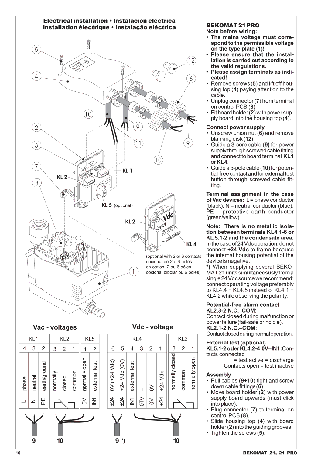
•The mains voltage must corre- spond to the permissible voltage on the type plate (1)!
•Please ensure that the instal- lation is carried out according to the valid regulations.
•Please assign terminals as indi- cated!
•Remove screws (5) and lift off hou- sing top (4) paying attention to the cable.
•Unplug connector (7)from terminal on control PCB (8).
•Fit board holder (2) with power sup- ply board into the housing top (4).
Connect power supply
•Unscrew union nut (6) and remove blanking disk (12)
•Guide a
•Guide a
Terminal assignment in the case of Vac devices: L = phase conductor (black), N = neutral conductor (blue), PE = protective earth conductor (green/yellow)
Note: There is no metallic isola- tion between terminals
*) When supplying several BEKO- MAT 21 units simultaneosusly from a single 24 Vdc source we recommend: connect operating voltage preferably to KL4.4 + KL4.5 instead of KL4.1 + KL4.2 while observing the polarity.
Potential-free alarm contact KL2.3-2 N.C.–COM:
Vac - voltages
| KL1 |
|
|
| KL2 |
|
|
|
|
|
|
|
|
4 | 3 | 2 |
| 3 | 2 | 1 |
phase | neutral | earth/ground |
| normally | closed | common |
|
|
|
|
|
|
|
L | N | PE |
|
|
|
|
|
|
|
|
|
|
|
KL5
12
0V 0Vnormally open IN1 external test
Vdc - voltage
|
| KL4 |
|
|
|
| KL2 |
| ||
6 | 5 | 4 | 3 | 2 | 1 |
| 3 | 2 |
| 1 |
0V (+24 Vdc) | +24 Vdc (0V) | external test | 0V | +24 Vdc |
| normally closed | common |
| normally open | |
|
|
|
|
|
|
|
|
|
|
|
±24 | ±24 | IN1 | 0TV | 0V | +24 |
|
|
|
|
|
|
|
|
|
|
|
|
|
|
|
|
Contact closed during malfunction or power failure
KL2.1-2 N.O.–COM:
Contactclosedduringnormaloperation.
External test (optional)
=test active = discharge Contacts open = test inactive
Assembly
•Pull cables (9+10) tight and screw down cable fittings(6)
•Move board holder (2) with power supply board upwards (must click into place).
•Plug connector (7) to terminal on control PCB (8).
•Slide housing top (4) with board holder (2) into the guiding grooves.
•Tighten the screws (5).
9 | 10 | 9 *) | 10 |
10 | BEKOMAT 21, 21 PRO |