24xx
Tractor 2 Cable Connectors
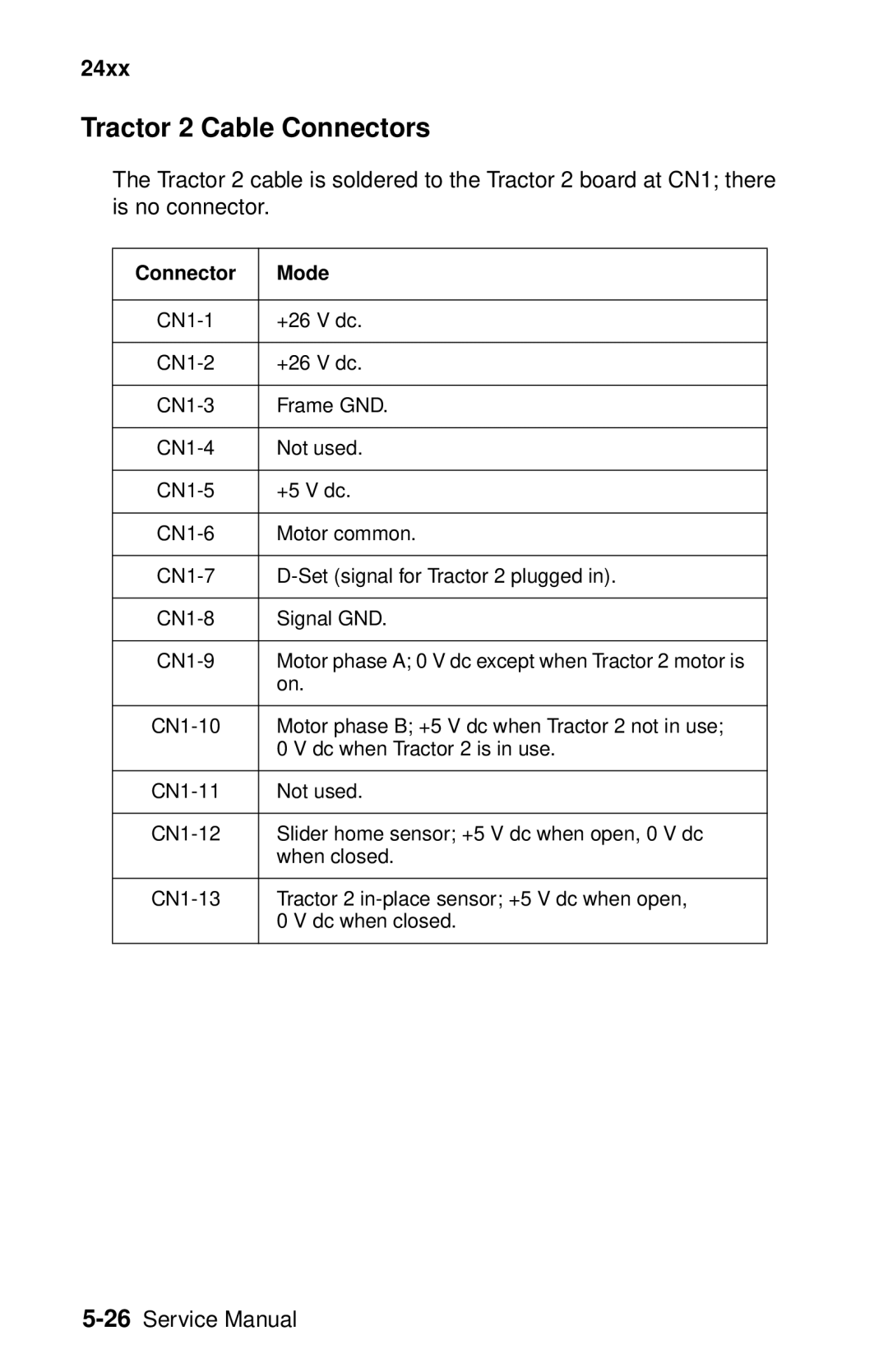
The Tractor 2 cable is soldered to the Tractor 2 board at CN1; there is no connector.
Connector | Mode |
|
|
+26 V dc. | |
|
|
+26 V dc. | |
|
|
Frame GND. | |
|
|
Not used. | |
|
|
+5 V dc. | |
|
|
Motor common. | |
|
|
|
|
Signal GND. | |
|
|
Motor phase A; 0 V dc except when Tractor 2 motor is | |
| on. |
|
|
Motor phase B; +5 V dc when Tractor 2 not in use; | |
| 0 V dc when Tractor 2 is in use. |
|
|
Not used. | |
|
|
Slider home sensor; +5 V dc when open, 0 V dc | |
| when closed. |
|
|
Tractor 2 | |
| 0 V dc when closed. |
|
|
