Contents
SVC MANUALGeneral
Contents
Safety Precautions Nomenclature
Part 1 General Information
Safety Precautions
Be sure not to do Be sure to follow the instruction
Part 1 General Information
Inspections after Repair
Nomenclature
Global Model Name
Code Type Code of Model Meaning
Part 2 Functions & Controls
Part 2 Functions & Controls
Function Description
Basic Mode Controls
Cooling Mode
Heating Mode
Intake air Temp Setting Temp
Healthy Dehumidification operation
Automatic operation
Auto changeover operation
Special Mode Controls
Energy saving operation in cooling mode
Jet Cool operation
Jet Heat operation
Auto cleaning operation
Indoor temp Operating Mode Setting temp
Utility Functions
Forced operation
Air volume control
Natural Air ControlAuto Wind
Chaos Swing
Sleep mode Auto control
Sleep timer operation for cooling cycle
Sleep timer operation for heating cycle
Auto restart
Protection Functions & Controls
Five Seconds Stand-by fan
Two Minutes Stand-by comp
Hot start
Automatic defrost
1 9,12kBtu/h Model
Starting to the defrosting operation
2 18,24,30kBtu/h Model
Defrosting Control Algorithm
Control algorithm of defrost completion
Power Relay Control
Inverter
Overheating Protection Power Module
Heat sink sensor failure error
Heat sink temperature control
Function
Total Current Control Over Current Protection
CT1 control
CT2 control
Model Cooling Heating KBtu/h 18~30 11A 12A 14A
DC Peak control
Discharge Pipe Temp Control
Inverter Compressor 18,24,30kBtu/h Model
Constant Compressor only 30kBtu/h Model
There can be two situations
Compressor working
Low Ambient control
12.1 9,12kBtu/h Model
12.2 18, 24, 30kBtu/h Model
Oil return control30kBtu/h Model
Oil equalizing control30kBtu/h Model
Operating Contion
Operation Process
Check before Test Run Test Run Flow chart Test Run Detail
Part 3 Test Run
Check before Test Run
Test Run Flow chart
Start
Pump Down Procedure
Test Run Detail
Settlement of outdoor unit
Evaluation of the performance
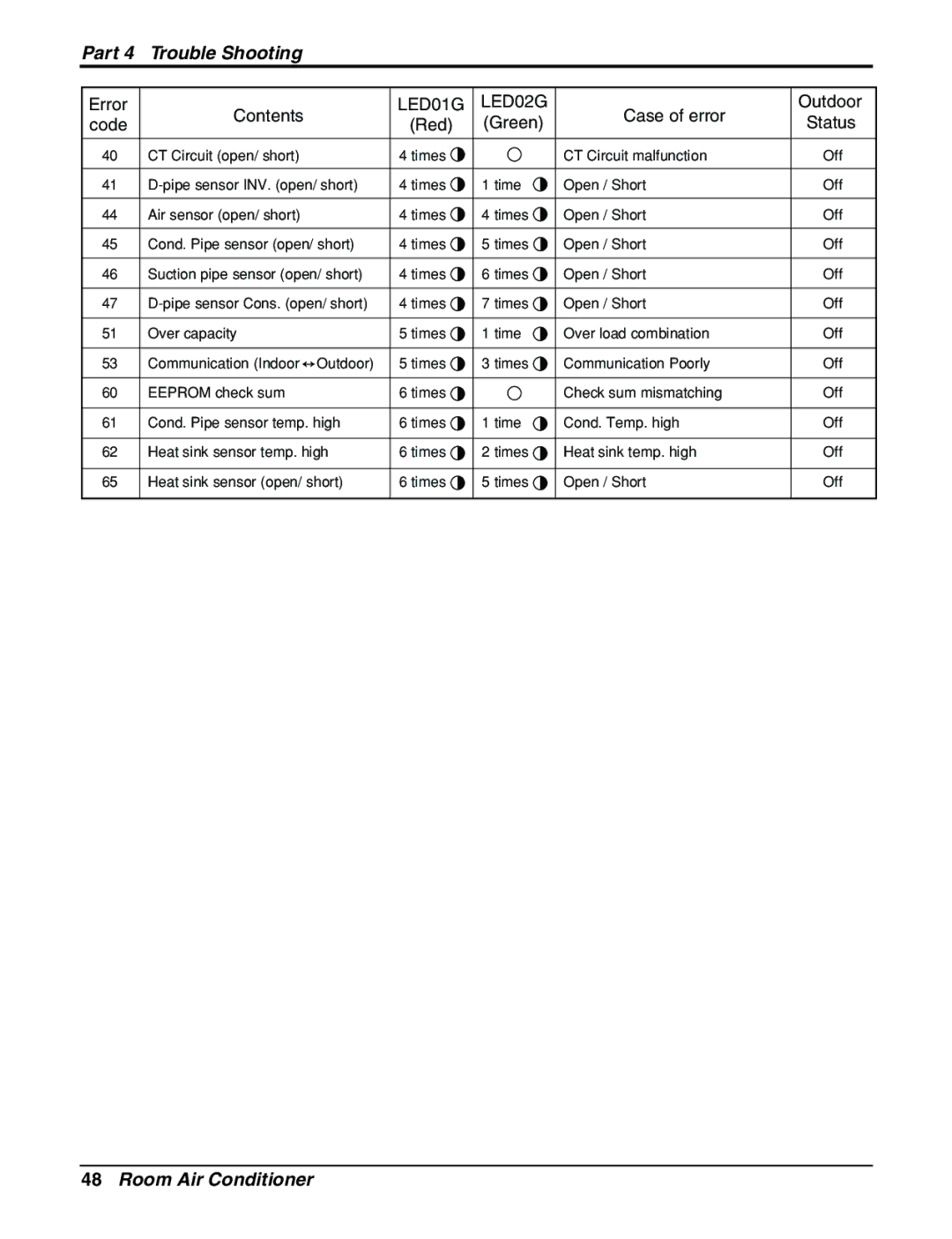
Part 4 Trouble Shooting
Way, 3-Way Valve
Way Valve Liquid Side
Procedure
Pumping Down
Air purging of the charge hose
Set the 2-way valve to the closed position
Evacuation All amount of refrigerant leaked
Mount the valve stem nuts and the service port nut
Gas Charging After Evacuation
Connect the charge hose to the charging cylinder
Purge the air from the charge hose
Cycle Troubleshooting Guide
Trouble analysis
Part 4 Trouble Shooting
Electronic Parts Troubleshooting Guide
Procedure Specification Remedy
Trouble
Compressor/Outdoor Fan dont operate 9~30kBtu/h Model
Compressor/Outdoor Fan dont operate 18, 24, 30kBtu/h Model
When indoor Fan does not operate.9~30kBtu/h Model
Error Indicator
Self-diagnosis Function
12kBtu/h Model
18,24,30kBtu/h Model Indoor Error
Outdoor Error
Error code Descrition
Red Green Status
Part Trouble Shooting
Troubleshooting Guide9,12kBtu/h Model
Description Cause of error Heat-sink Temp. is over
Earth port
DC Peak Error
Description Cause of error Over current Error
Description Cause of error Indoor fan is locked
Description Cause of error Pipe TH. is short or
Troubleshooting CH01, CH02, CH06
Check Point
Part 4 Trouble Shooting
Troubleshooting CH05, CH53
Troubleshooting CH21
Comp
Copper Comp pipe
Troubleshooting CH21, CH22
Troubleshooting CH23, CH28
Troubleshooting CH24, CH25
Troubleshooting CH26, CH27
Troubleshooting CH32, CH33, CH40
Troubleshooting CH41, CH44, CH45, CH46, CH47, CH65
Troubleshooting CH51, CH60
Troubleshooting CH61, CH62
No MFL41161601 August