Connect the general AC cables in the following order:
AC output single phase 240VAC
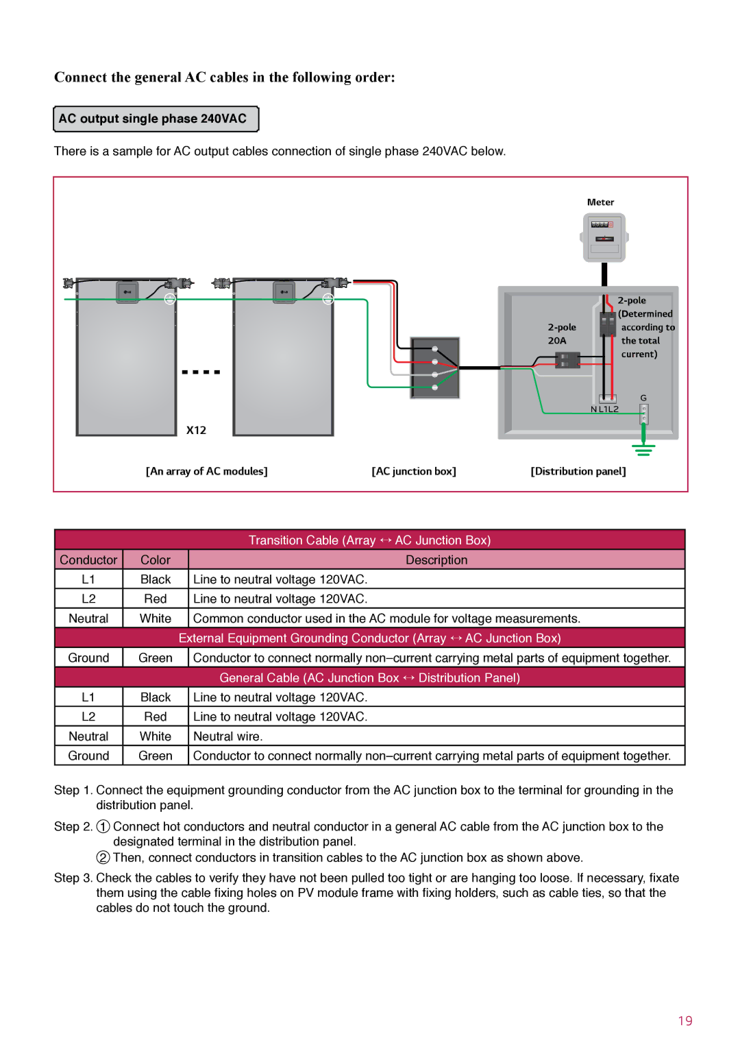
There is a sample for AC output cables connection of single phase 240VAC below.
Meter
0 ![]() 0
0 ![]() 0
0 ![]() 0
0 ![]()
![]() 0
0
|
|
| |
|
|
| (Determined |
|
| according to | |
|
| 20A | the total |
|
|
| current) |
|
|
| G |
|
|
| N L1L2 |
X12 |
|
|
|
[An array of AC modules] | [AC junction box] | [Distribution panel] | |
|
| Transition Cable (Array ÷ AC Junction Box) |
Conductor | Color | Description |
L1 | Black | Line to neutral voltage 120VAC. |
L2 | Red | Line to neutral voltage 120VAC. |
Neutral | White | Common conductor used in the AC module for voltage measurements. |
|
| External Equipment Grounding Conductor (Array ÷ AC Junction Box) |
Ground | Green | Conductor to connect normally |
|
| General Cable (AC Junction Box ÷ Distribution Panel) |
L1 | Black | Line to neutral voltage 120VAC. |
L2 | Red | Line to neutral voltage 120VAC. |
Neutral | White | Neutral wire. |
Ground | Green | Conductor to connect normally |
Step 1. Connect the equipment grounding conductor from the AC junction box to the terminal for grounding in the distribution panel.
Step 2. 1
2
Step 3. Check the cables to verify they have not been pulled too tight or are hanging too loose. If necessary, fixate them using the cable fixing holes on PV module frame with fixing holders, such as cable ties, so that the cables do not touch the ground.
19