3-5 Wiring Diagram of AC Module System
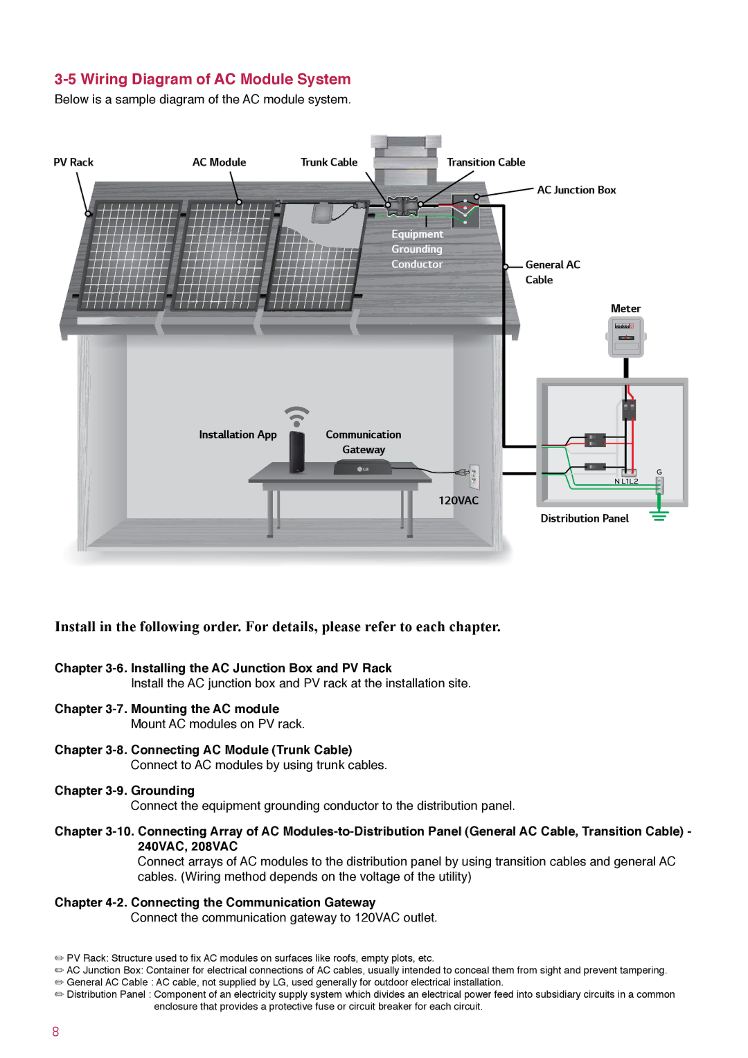
Below is a sample diagram of the AC module system.
PV Rack | AC Module | Trunk Cable | Transition Cable |
![]()
![]() AC Junction Box
AC Junction Box
|
|
|
|
Equipment |
|
| |
Grounding |
|
| |
Conductor |
| General AC | |
| |||
|
|
| Cable |
Meter
![]() 0
0 ![]() 0
0 ![]() 0
0 ![]() 0 0
0 0
Installation App | Communication |
| Gateway |
G
N L1L2
120VAC![]()
![]() Distribution Panel
Distribution Panel ![]()
Install in the following order. For details, please refer to each chapter.
Chapter
Install the AC junction box and PV rack at the installation site.
Chapter
Mount AC modules on PV rack.
Chapter
Connect to AC modules by using trunk cables.
Chapter
Connect the equipment grounding conductor to the distribution panel.
Chapter
Connect arrays of AC modules to the distribution panel by using transition cables and general AC cables. (Wiring method depends on the voltage of the utility)
Chapter 4-2. Connecting the Communication Gateway
Connect the communication gateway to 120VAC outlet.
/PV Rack: Structure used to fix AC modules on surfaces like roofs, empty plots, etc.
/AC Junction Box: Container for electrical connections of AC cables, usually intended to conceal them from sight and prevent tampering.
/General AC Cable : AC cable, not supplied by LG, used generally for outdoor electrical installation.
/Distribution Panel : Component of an electricity supply system which divides an electrical power feed into subsidiary circuits in a common enclosure that provides a protective fuse or circuit breaker for each circuit.
8