System Setup (Cont.)
(Continued from previous page)
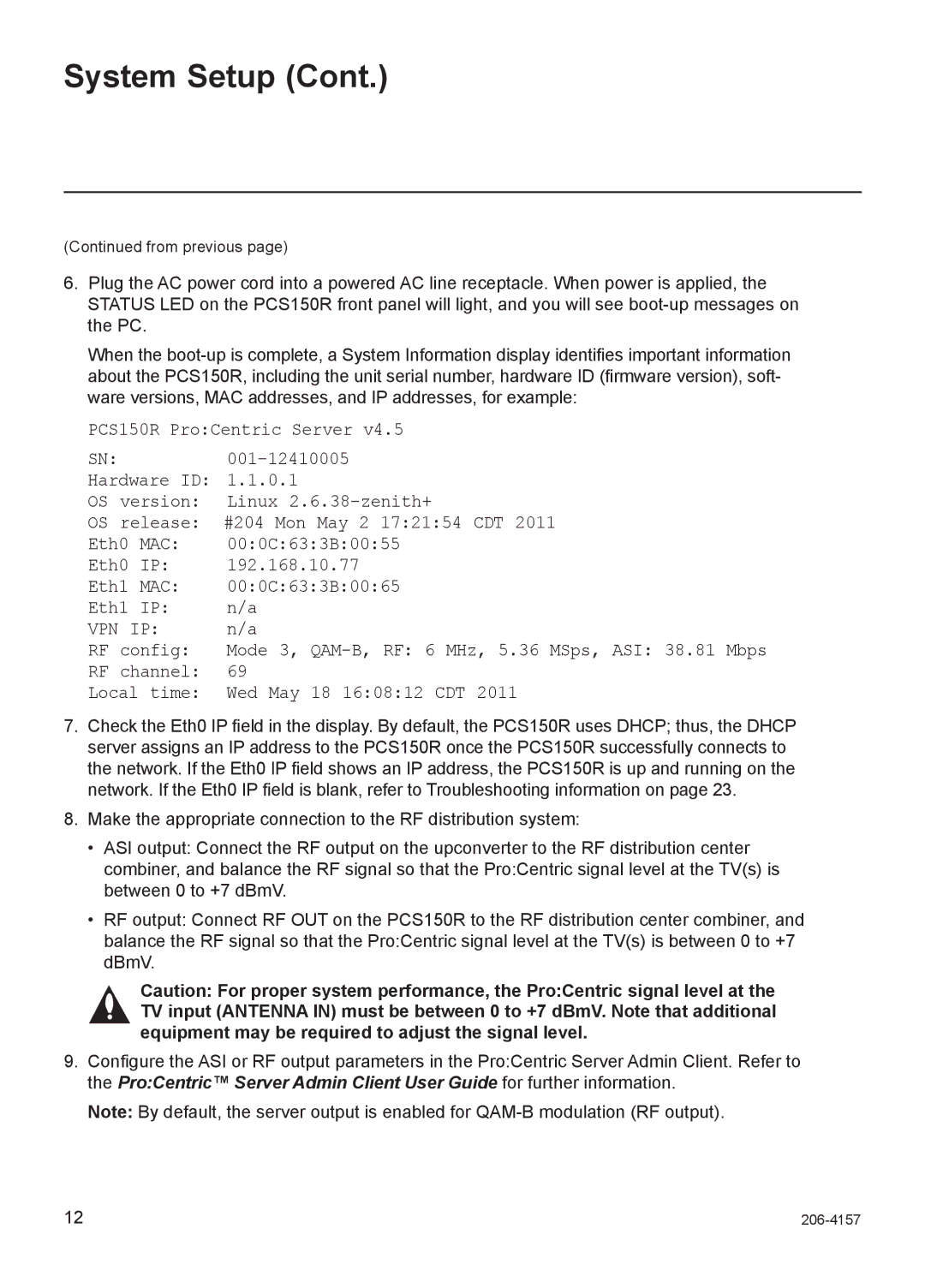
6.Plug the AC power cord into a powered AC line receptacle. When power is applied, the STATUS LED on the PCS150R front panel will light, and you will see
When the
PCS150R Pro:Centric Server v4.5
SN:
Hardware ID: 1.1.0.1
OS version: Linux
OS release: #204 Mon May 2 17:21:54 CDT 2011
Eth0 MAC: 00:0C:63:3B:00:55
Eth0 IP: 192.168.10.77
Eth1 MAC: 00:0C:63:3B:00:65
Eth1 IP: n/a
VPN IP: n/a
RF config: Mode 3,
RF channel: 69
Local time: Wed May 18 16:08:12 CDT 2011
7.Check the Eth0 IP field in the display. By default, the PCS150R uses DHCP; thus, the DHCP server assigns an IP address to the PCS150R once the PCS150R successfully connects to the network. If the Eth0 IP field shows an IP address, the PCS150R is up and running on the network. If the Eth0 IP field is blank, refer to Troubleshooting information on page 23.
8.Make the appropriate connection to the RF distribution system:
•ASI output: Connect the RF output on the upconverter to the RF distribution center combiner, and balance the RF signal so that the Pro:Centric signal level at the TV(s) is between 0 to +7 dBmV.
•RF output: Connect RF OUT on the PCS150R to the RF distribution center combiner, and balance the RF signal so that the Pro:Centric signal level at the TV(s) is between 0 to +7 dBmV.
Caution: For proper system performance, the Pro:Centric signal level at the TV input (ANTENNA IN) must be between 0 to +7 dBmV. Note that additional equipment may be required to adjust the signal level.
9.Configure the ASI or RF output parameters in the Pro:Centric Server Admin Client. Refer to the Pro:Centric™ Server Admin Client User Guide for further information.
Note: By default, the server output is enabled for
12 |
