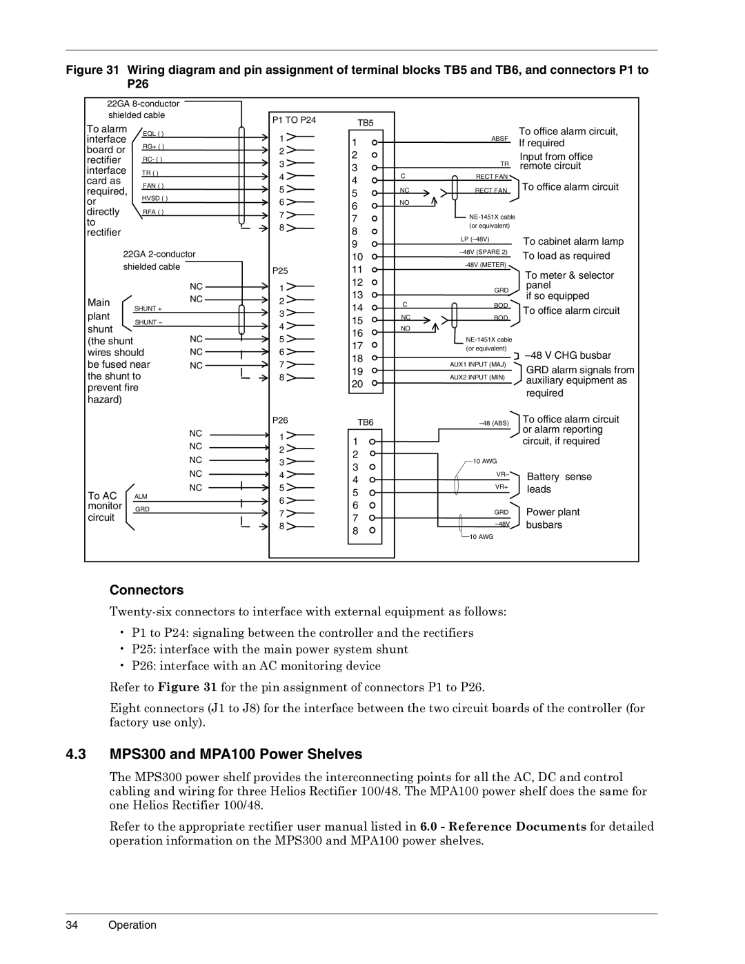
Figure 31 Wiring diagram and pin assignment of terminal blocks TB5 and TB6, and connectors P1 to P26

22GA 8-conductor


shielded cable


To alarm


EQL ( )


NT6C43PAinterface


RG+ ( )


or


board or


NT6C43PB


RC- ( )


rectifier


rectifier


TR ( )


interface


interface


card as


FAN ( )


card as


required,


required,


HVSD ( )


or


or directly


directly


RFA ( )


to rectifier


to


rectifier


22GA 2-conductor

shielded cable


NC

Main


NC

SHUNT +


plant


SHUNT –


shunt


NC

(the shunt


wires should

NC

be fused near

NC

the shunt to


prevent fire


hazard)


NC

NC

NC

NC

NC

To AC

ALM

monitor

GRD

circuit


such as


P1 TO P24

1

2

3

4

5

6

7

8

P25

1

2

3

4

5

6

7

8

P26

1

2

3

4

5

6

7

8

TB5

1

2

3

4

5

6

7

8

9

10

11

12

13

14

15

16

17

18

19

20

TB6

1

2

3

4

5

6

7

8

C

NC NO

C

NC NO

ABSF

To office alarm circuit,

If required


Input from office

TR

remote circuit

RECT FAN


RECT FAN

To office alarm circuit

NE-1451X cable


(or equivalent)


LP (–48V)

To cabinet alarm lamp


–48V (SPARE 2)

To load as required

-48V (METER)


To meter & selector

GRD

panel


if so equipped


BOD

To office alarm circuit

BOD


NE-1451X cable


(or equivalent)

–48 V CHG busbar

AUX1 INPUT (MAJ)

GRD alarm signals from

AUX2 INPUT (MIN)

auxiliary equipment as


required

–48 (ABS)

To office alarm circuit


or alarm reporting


circuit, if required

10 AWG


VR–

Battery sense


VR+

leads


GRD

Power plant

–48V

busbars

10 AWG


Connectors

Twenty-six connectors to interface with external equipment as follows:

P1 to P24: signaling between the controller and the rectifiers

P25: interface with the main power system shunt

P26: interface with an AC monitoring device

Refer to Figure 31 for the pin assignment of connectors P1 to P26.

Eight connectors (J1 to J8) for the interface between the two circuit boards of the controller (for factory use only).

4.3MPS300 and MPA100 Power Shelves

The MPS300 power shelf provides the interconnecting points for all the AC, DC and control cabling and wiring for three Helios Rectifier 100/48. The MPA100 power shelf does the same for one Helios Rectifier 100/48.

Refer to the appropriate rectifier user manual listed in 6.0 - Reference Documents for detailed operation information on the MPS300 and MPA100 power shelves.

34 Operation

Page 40
Image 40
Liebert 3000, 4000, 6000 A, 1500 user manual MPS300 and MPA100 Power Shelves, Connectors

1500, 6000 A, 4000, 3000 specifications

The Liebert 3000 is a cutting-edge power protection solution designed to provide reliable and efficient backup power for critical applications. This uninterruptible power supply (UPS) system is engineered to safeguard sensitive electronic equipment from power disturbances, ensuring uninterrupted operations in data centers, telecommunications, and industrial environments.

One of the standout features of the Liebert 3000 is its high-efficiency design. With an efficiency rating of up to 94%, the system minimizes energy loss, resulting in lower operational costs and a reduced carbon footprint. This is particularly important in today's environmentally conscious climate, as organizations strive to meet sustainability goals while maintaining top-tier performance.

The Liebert 3000 employs advanced technologies to enhance its functionality. It incorporates online double-conversion technology, which provides a continuous supply of clean and regulated power. This technology ensures that connected loads receive stable voltage and frequency, shielding them from voltage spikes, sags, and outages. Additionally, the UPS offers features such as automatic battery testing, which helps ensure peak battery performance and reliability.

Another key characteristic of the Liebert 3000 is its modular design, allowing for flexible scalability. This means that organizations can easily expand the capacity of their UPS system as their power needs grow, without the need for extensive system overhauls. The modular architecture also facilitates simplified maintenance and reduces downtime, as individual modules can be serviced without interrupting power to the critical load.

The system is equipped with comprehensive monitoring and management capabilities. The Liebert 3000 provides real-time data on power usage, battery status, and system performance, enabling facility managers to make informed decisions and proactively address potential issues. The integration of remote management tools allows for seamless monitoring from anywhere, providing peace of mind for operators.

Overall, the Liebert 3000 combines high efficiency, advanced technology, and flexible design to deliver a robust power protection solution. Its reliability and performance make it a preferred choice for organizations seeking to protect their critical infrastructure while enhancing operational efficiency and sustainability. As businesses continue to rely on technology for their everyday operations, the Liebert 3000 stands out as a dependable safeguard against the uncertainties of power quality.