Table 3 Table
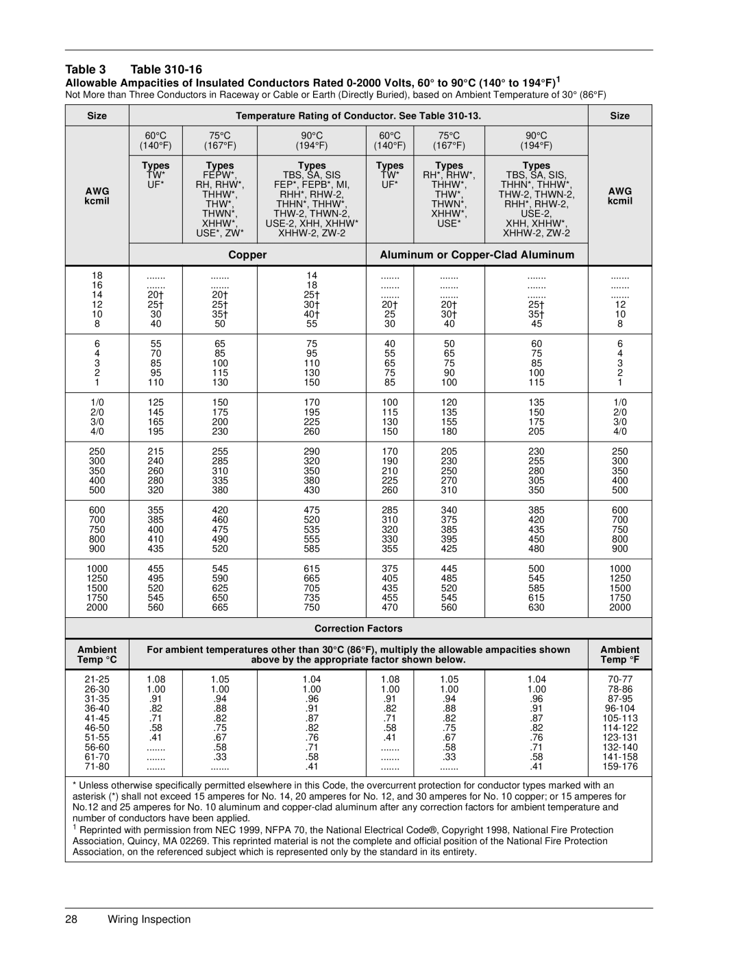
Allowable Ampacities of Insulated Conductors Rated
Not More than Three Conductors in Raceway or Cable or Earth (Directly Buried), based on Ambient Temperature of 30° (86°F)
Size | Temperature Rating of Conductor. See Table |
| Size | |||||
|
|
|
|
|
|
|
|
|
|
| 60°C | 75°C | 90°C | 60°C | 75°C | 90°C |
|
|
| (140°F) | (167°F) | (194°F) | (140°F) | (167°F) | (194°F) |
|
|
|
|
|
|
|
|
|
|
|
| Types | Types | Types | Types | Types | Types |
|
|
| TW* | FEPW*, | TBS, SA, SIS | TW* | RH*, RHW*, | TBS, SA, SIS, |
|
AWG | UF* | RH, RHW*, | FEP*, FEPB*, MI, | UF* | THHW*, | THHN*, THHW*, | AWG | |
| THHW*, | RHH*, |
| THW*, | ||||
kcmil |
|
| kcmil | |||||
| THW*, | THHN*, THHW*, |
| THWN*, | RHH*, | |||
|
|
| THWN*, |
| XHHW*, |
| ||
|
|
| XHHW*, |
| USE* | XHH, XHHW*, |
| |
|
|
| USE*, ZW* |
|
|
| ||
|
|
|
|
|
|
|
|
|
|
| Copper |
| Aluminum or |
| |||
|
|
|
|
|
|
|
|
|
18 | ....... | ....... |
| 14 | ....... | ....... | ....... | ....... |
16 | ....... | ....... |
| 18 | ....... | ....... | ....... | ....... |
14 | 20† | 20† |
| 25† | ....... | ....... | ....... | ....... |
12 | 25† | 25† |
| 30† | 20† | 20† | 25† | 12 |
10 | 30 | 35† |
| 40† | 25 | 30† | 35† | 10 |
8 | 40 | 50 |
| 55 | 30 | 40 | 45 | 8 |
|
|
|
|
|
|
|
|
|
6 | 55 | 65 |
| 75 | 40 | 50 | 60 | 6 |
4 | 70 | 85 |
| 95 | 55 | 65 | 75 | 4 |
3 | 85 | 100 |
| 110 | 65 | 75 | 85 | 3 |
2 | 95 | 115 |
| 130 | 75 | 90 | 100 | 2 |
1 | 110 | 130 |
| 150 | 85 | 100 | 115 | 1 |
|
|
|
|
|
|
|
|
|
1/0 | 125 | 150 |
| 170 | 100 | 120 | 135 | 1/0 |
2/0 | 145 | 175 |
| 195 | 115 | 135 | 150 | 2/0 |
3/0 | 165 | 200 |
| 225 | 130 | 155 | 175 | 3/0 |
4/0 | 195 | 230 |
| 260 | 150 | 180 | 205 | 4/0 |
|
|
|
|
|
|
|
|
|
250 | 215 | 255 |
| 290 | 170 | 205 | 230 | 250 |
300 | 240 | 285 |
| 320 | 190 | 230 | 255 | 300 |
350 | 260 | 310 |
| 350 | 210 | 250 | 280 | 350 |
400 | 280 | 335 |
| 380 | 225 | 270 | 305 | 400 |
500 | 320 | 380 |
| 430 | 260 | 310 | 350 | 500 |
|
|
|
|
|
|
|
|
|
600 | 355 | 420 |
| 475 | 285 | 340 | 385 | 600 |
700 | 385 | 460 |
| 520 | 310 | 375 | 420 | 700 |
750 | 400 | 475 |
| 535 | 320 | 385 | 435 | 750 |
800 | 410 | 490 |
| 555 | 330 | 395 | 450 | 800 |
900 | 435 | 520 |
| 585 | 355 | 425 | 480 | 900 |
|
|
|
|
|
|
|
|
|
1000 | 455 | 545 |
| 615 | 375 | 445 | 500 | 1000 |
1250 | 495 | 590 |
| 665 | 405 | 485 | 545 | 1250 |
1500 | 520 | 625 |
| 705 | 435 | 520 | 585 | 1500 |
1750 | 545 | 650 |
| 735 | 455 | 545 | 615 | 1750 |
2000 | 560 | 665 |
| 750 | 470 | 560 | 630 | 2000 |
|
|
|
|
|
|
|
|
|
Correction Factors
Ambient | For ambient temperatures other than 30°C (86°F), multiply the allowable ampacities shown | Ambient | ||||||
Temp °C |
|
| above by the appropriate factor shown below. |
| Temp °F | |||
|
|
|
|
|
|
|
|
|
1.08 | 1.05 |
| 1.04 | 1.08 | 1.05 | 1.04 | ||
1.00 | 1.00 |
| 1.00 | 1.00 | 1.00 | 1.00 | ||
.91 | .94 |
| .96 | .91 | .94 | .96 | ||
.82 | .88 |
| .91 | .82 | .88 | .91 | ||
.71 | .82 |
| .87 | .71 | .82 | .87 | ||
.58 | .75 |
| .82 | .58 | .75 | .82 | ||
.41 | .67 |
| .76 | .41 | .67 | .76 | ||
....... | .58 |
| .71 | ....... | .58 | .71 | ||
....... | .33 |
| .58 | ....... | .33 | .58 | ||
....... | ....... |
| .41 | ....... | ....... | .41 | ||
|
|
|
|
|
|
|
|
|
* Unless otherwise specifically permitted elsewhere in this Code, the overcurrent protection for conductor types marked with an asterisk (*) shall not exceed 15 amperes for No. 14, 20 amperes for No. 12, and 30 amperes for No. 10 copper; or 15 amperes for No.12 and 25 amperes for No. 10 aluminum and
1 Reprinted with permission from NEC 1999, NFPA 70, the National Electrical Code®, Copyright 1998, National Fire Protection Association, Quincy, MA 02269. This reprinted material is not the complete and official position of the National Fire Protection Association, on the referenced subject which is represented only by the standard in its entirety.
28 Wiring Inspection