7.1Preferred Grounding Configuration, 480 or 600 VAC Input and Output, Isolated Power Distribution Units, Wye-Connected Service
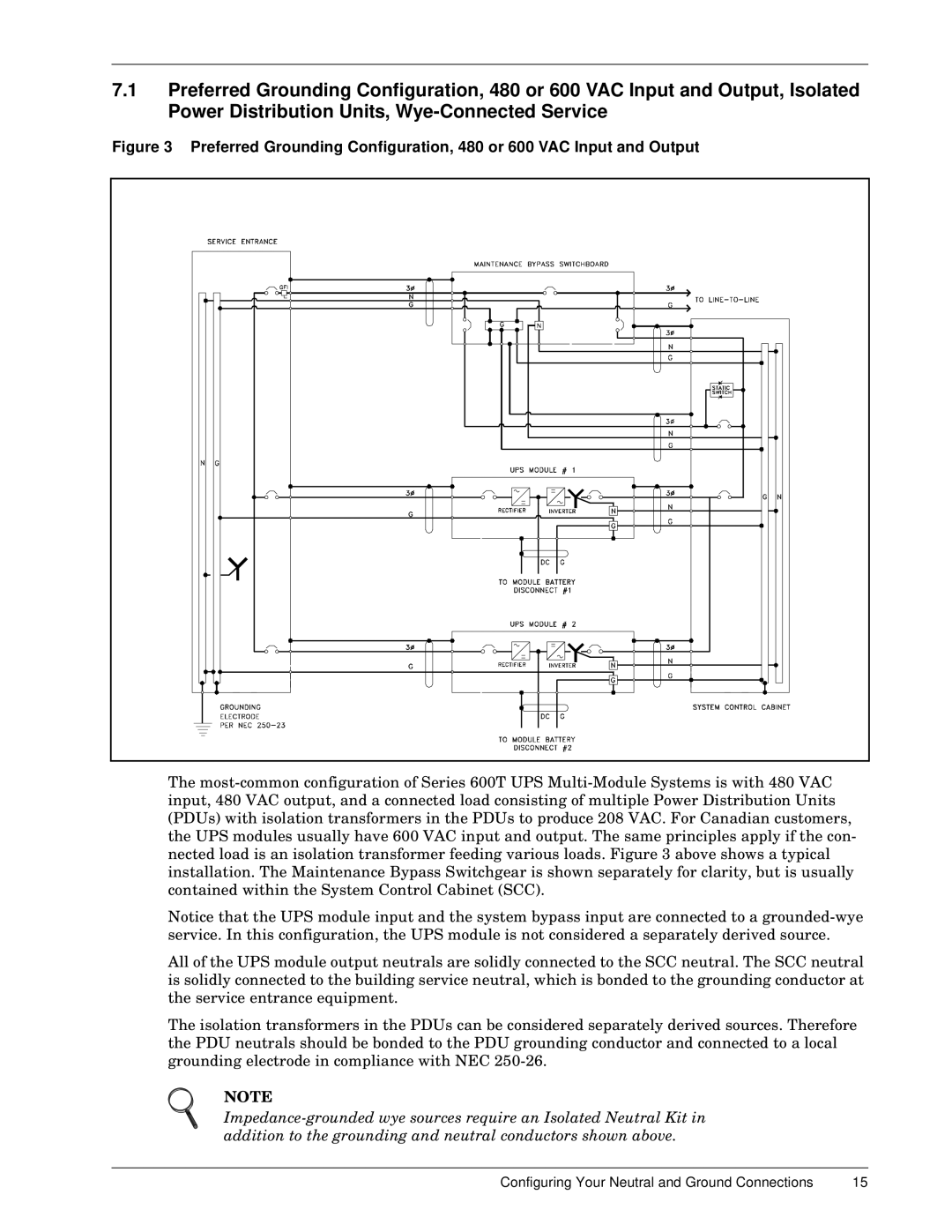
Figure 3 Preferred Grounding Configuration, 480 or 600 VAC Input and Output
The most-common configuration of Series 600T UPS Multi-Module Systems is with 480 VAC input, 480 VAC output, and a connected load consisting of multiple Power Distribution Units (PDUs) with isolation transformers in the PDUs to produce 208 VAC. For Canadian customers, the UPS modules usually have 600 VAC input and output. The same principles apply if the con- nected load is an isolation transformer feeding various loads. Figure 3 above shows a typical installation. The Maintenance Bypass Switchgear is shown separately for clarity, but is usually contained within the System Control Cabinet (SCC).
Notice that the UPS module input and the system bypass input are connected to a grounded-wye service. In this configuration, the UPS module is not considered a separately derived source.
All of the UPS module output neutrals are solidly connected to the SCC neutral. The SCC neutral is solidly connected to the building service neutral, which is bonded to the grounding conductor at the service entrance equipment.
The isolation transformers in the PDUs can be considered separately derived sources. Therefore the PDU neutrals should be bonded to the PDU grounding conductor and connected to a local grounding electrode in compliance with NEC 250-26.
NOTE
Impedance-grounded wye sources require an Isolated Neutral Kit in addition to the grounding and neutral conductors shown above.
Configuring Your Neutral and Ground Connections | 15 |