RACK-MOUNT CONVERSION DIAGRAMS
Top |
|
|
|
|
Cover | Flange | Rubber |
|
|
Screws |
|
| ||
Screws |
|
| ||
| Feet |
|
| |
|
|
|
| |
|
| ! | Fault |
|
|
| Lift here to | E | BYPASS |
|
| D | UPS | |
|
| change | ||
|
| ON | ||
|
| orientation of | C | BATTERY |
|
| display template | B | AC |
| Aerial View | + - | A | INPUT |
|
| |||
| w/top cover removed |
|
|
|
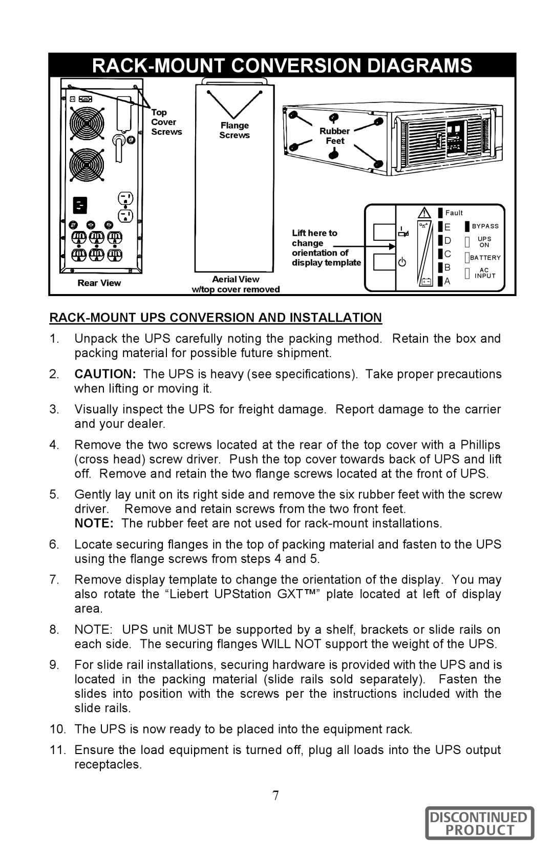
RACK-MOUNT UPS CONVERSION AND INSTALLATION
1.Unpack the UPS carefully noting the packing method. Retain the box and packing material for possible future shipment.
2.CAUTION: The UPS is heavy (see specifications). Take proper precautions when lifting or moving it.
3.Visually inspect the UPS for freight damage. Report damage to the carrier and your dealer.
4.Remove the two screws located at the rear of the top cover with a Phillips (cross head) screw driver. Push the top cover towards back of UPS and lift off. Remove and retain the two flange screws located at the front of UPS.
5.Gently lay unit on its right side and remove the six rubber feet with the screw driver. Remove and retain screws from the two front feet.
NOTE: The rubber feet are not used for
6.Locate securing flanges in the top of packing material and fasten to the UPS using the flange screws from steps 4 and 5.
7.Remove display template to change the orientation of the display. You may also rotate the “Liebert UPStation GXT™” plate located at left of display area.
8.NOTE: UPS unit MUST be supported by a shelf, brackets or slide rails on each side. The securing flanges WILL NOT support the weight of the UPS.
9.For slide rail installations, securing hardware is provided with the UPS and is located in the packing material (slide rails sold separately). Fasten the slides into position with the screws per the instructions included with the slide rails.
10.The UPS is now ready to be placed into the equipment rack.
11.Ensure the load equipment is turned off, plug all loads into the UPS output receptacles.
7
DISCONTINUED
PRODUCT