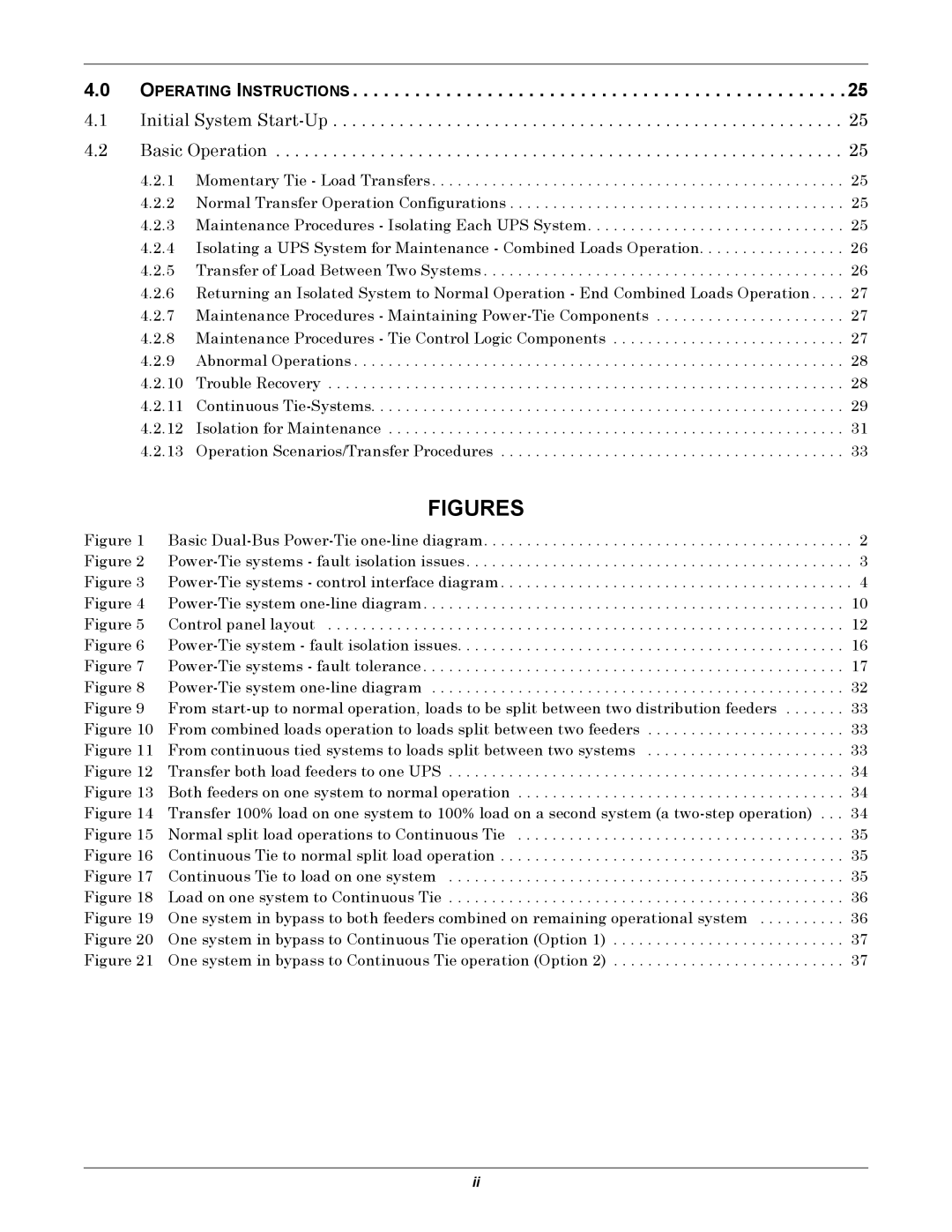
4.0 OPERATING INSTRUCTIONS . . . . . . . . . . . . . . . . . . . . . . . . . . . . . . . . . . . . . . . . . . . . . . . .25
4.1 Initial System Start-Up . . . . . . . . . . . . . . . . . . . . . . . . . . . . . . . . . . . . . . . . . . . . . . . . . . . . . . 25 4.2 Basic Operation . . . . . . . . . . . . . . . . . . . . . . . . . . . . . . . . . . . . . . . . . . . . . . . . . . . . . . . . . . . . 25
4.2.1 Momentary Tie - Load Transfers . . . . . . . . . . . . . . . . . . . . . . . . . . . . . . . . . . . . . . . . . . . . . . . . 25 4.2.2 Normal Transfer Operation Configurations . . . . . . . . . . . . . . . . . . . . . . . . . . . . . . . . . . . . . . . 25 4.2.3 Maintenance Procedures - Isolating Each UPS System. . . . . . . . . . . . . . . . . . . . . . . . . . . . . . 25 4.2.4 Isolating a UPS System for Maintenance - Combined Loads Operation. . . . . . . . . . . . . . . . . 26 4.2.5 Transfer of Load Between Two Systems . . . . . . . . . . . . . . . . . . . . . . . . . . . . . . . . . . . . . . . . . . 26 4.2.6 Returning an Isolated System to Normal Operation - End Combined Loads Operation . . . . 27 4.2.7 Maintenance Procedures - Maintaining
| FIGURES |
|
Figure 1 | Basic | . 2 |
Figure 2 | . 3 | |
Figure 3 | . 4 | |
Figure 4 | 10 | |
Figure 5 | Control panel layout | 12 |
Figure 6 | 16 | |
Figure 7 | 17 | |
Figure 8 | 32 | |
Figure 9 | From | 33 |
Figure 10 | From combined loads operation to loads split between two feeders | 33 |
Figure 11 | From continuous tied systems to loads split between two systems | 33 |
Figure 12 | Transfer both load feeders to one UPS | 34 |
Figure 13 | Both feeders on one system to normal operation | 34 |
Figure 14 | Transfer 100% load on one system to 100% load on a second system (a | |
Figure 15 | Normal split load operations to Continuous Tie | 35 |
Figure 16 | Continuous Tie to normal split load operation | 35 |
Figure 17 | Continuous Tie to load on one system | 35 |
Figure 18 | Load on one system to Continuous Tie | 36 |
Figure 19 | One system in bypass to both feeders combined on remaining operational system | 36 |
Figure 20 | One system in bypass to Continuous Tie operation (Option 1) | 37 |
Figure 21 | One system in bypass to Continuous Tie operation (Option 2) | 37 |
ii
