|
|
| Operating Instructions |
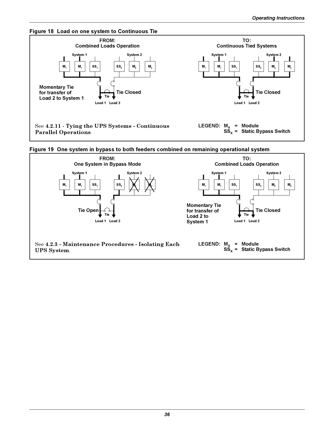
Figure 18 Load on one system to Continuous Tie |
|
| |
| FROM: |
| TO: |
Combined Loads Operation | Continuous Tied Systems | ||
System 1 | System 2 | System 1 | System 2 |
M1
M1
SS1
SS2
M2
M2
M1
M1
SS1
SS2
M2
M2
Momentary Tie for transfer of Load 2 to System 1
![]() Tie Closed
Tie Closed
Tie
Load 1 Load 2
![]() Tie Closed
Tie Closed
Tie
Load 1 Load 2
See 4.2.11 - Tying the UPS Systems - Continuous | LEGEND: Mx = | Module |
Parallel Operations. | SSx = | Static Bypass Switch |
Figure 19 One system in bypass to both feeders combined on remaining operational system
M1
FROM:
One System in Bypass Mode
System 1 |
|
|
|
|
| System 2 |
|
| ||||||
|
|
|
|
|
|
|
|
|
|
|
|
|
|
|
| M1 |
| SS1 |
| SS2 |
|
|
|
|
| ||||
|
|
|
|
|
|
|
|
|
|
|
|
|
|
|
|
|
|
|
|
|
|
|
|
|
|
|
|
|
|
M1
TO:
Combined Loads Operation
System 1 |
|
|
|
|
| System 2 | ||||||
|
|
|
|
|
|
|
|
|
|
|
|
|
| M1 |
| SS1 |
| SS2 |
| M2 |
| ||||
|
|
|
|
|
|
|
|
|
|
|
|
|
|
|
|
|
|
|
|
|
|
|
|
|
|
M2
Tie Open |
| Momentary Tie |
| Tie Closed |
| for transfer of |
| ||
Tie | Load 2 to | Tie | ||
Load 1 | Load 2 | System 1 | Load 1 | Load 2 |
See 4.2.3 - Maintenance Procedures - Isolating Each | LEGEND: Mx = | Module |
UPS System. | SSx = | Static Bypass Switch |
36