7084284-03 specifications
The Liebherr 7084284-03 is a high-quality component designed for use in various applications, particularly in the construction and material handling sectors. Known for its reliability and efficiency, this part reflects Liebherr's commitment to robust engineering and innovation.One of the core features of the Liebherr 7084284-03 is its durability, constructed from premium materials that withstand the rigors of demanding environments. This makes it ideal for heavy-duty applications, whether used in cranes, excavators, or other machinery. The resilience of this component ensures a longer service life, reducing downtime and maintenance costs.
In terms of technology, the Liebherr 7084284-03 integrates advanced mechanical systems designed to enhance operational efficiency. It employs cutting-edge design techniques that optimize performance while minimizing wear and tear. This precision engineering contributes to the smooth operation of machinery, ensuring that tasks are completed efficiently and safely.
The component is also designed with ease of installation and maintenance in mind. Its user-friendly design allows for quick replacements or repairs, which is critical in environments where time is of the essence. Maintenance becomes straightforward, allowing operators to focus more on productivity rather than on equipment issues.
Another notable characteristic of the Liebherr 7084284-03 is its compatibility with a wide range of machinery. This versatility means that it can be integrated seamlessly into existing setups, providing a cost-effective solution for those looking to enhance their equipment's capabilities without extensive modifications.
Moreover, the component is engineered to operate under various environmental conditions, including extreme temperatures and humidity levels. Its performance is tested rigorously to ensure it meets industry standards, giving operators the confidence that it will perform reliably under any conditions.
Overall, the Liebherr 7084284-03 embodies the high standards of quality and innovation that Liebherr is known for. With its impressive features, advanced technologies, and robust characteristics, it stands out as a component that enhances the reliability and efficiency of machinery in the construction and material handling industry. As businesses seek to improve their operational capabilities, components like the Liebherr 7084284-03 are invaluable assets.

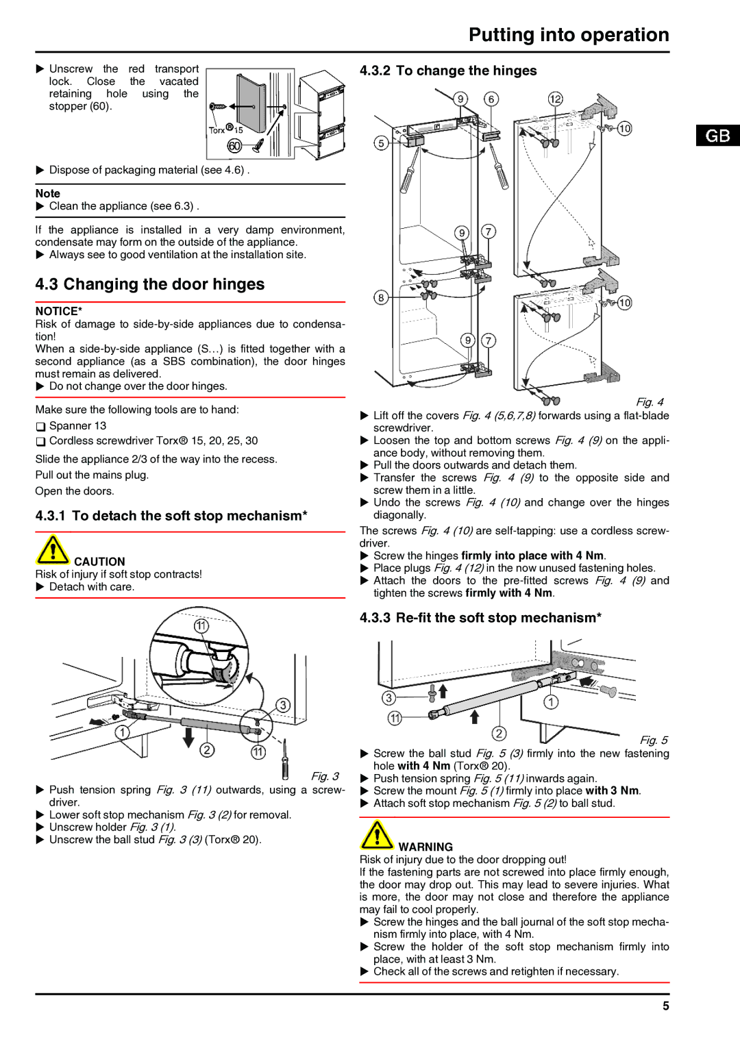
 Fig. 3
  Fig. 5