INSTALLATION | ||
|
|
|
SAFETY PRECAUTION
ELECTRIC SHOCK can kill.
•Only qualified personnel should per- form this installation.
•Turn off the input power to the power source at the disconnect switch or fuse box before working on this equipment. Turn off the input power to any other equipment connected to the welding system at the disconnect switch or fuse box before work- ing on this equipment.
•Do not touch electrically hot parts.
•Always connect the Power Wave grounding lug (located inside the reconnect input access door) to a proper safety (Earth) ground.
WIRE FEEDER TO POWER SOURCE CONFIGURATIONS
The Wire Feeder is equipped to operate in the vertical or horizontal position. It is shipped ready for use in the in the vertical position.
MOUNTING ON TOP OF THE POWER SOURCE
The Wire Feeder is shipped with the vertical mounting bracket installed on the bottom of the Feeder. The Feeder must be placed on top (right side) of the Power Source such that the bolt on the mounting bracket goes thru the hole in the Power Source’s Lift Bail and the front hole on the right front foot of the mounting bracket is placed over the weld stud on the roof of the Power Source. Use the Wing Nut/washer assembly provided to secure the Feeder to the Power Source.
Note: The Wire Feeder can also be mounted horizon- tally. See ACCESSORIES section for information on the Optional Horizontal Mounting Bracket.
HANGING
The Wire Feeder is equipped with 2 insulated Lifting Eyes for hanging the Feeder. It is recommended that the Lifting Eyes always be used when hanging the Feeder. The Lifting Handles should be used for short term carrying of the Feeder
Note: A longer or additional Control Cable may be required when hanging the Feeder. See ACCES- SORIES section for information on optional Control Cables.
ON THE FLOOR
The Wire Feeder is equipped with aluminum skids which protect the enclosure when the Feeder is placed on the floor in either the horizontal or vertical position.
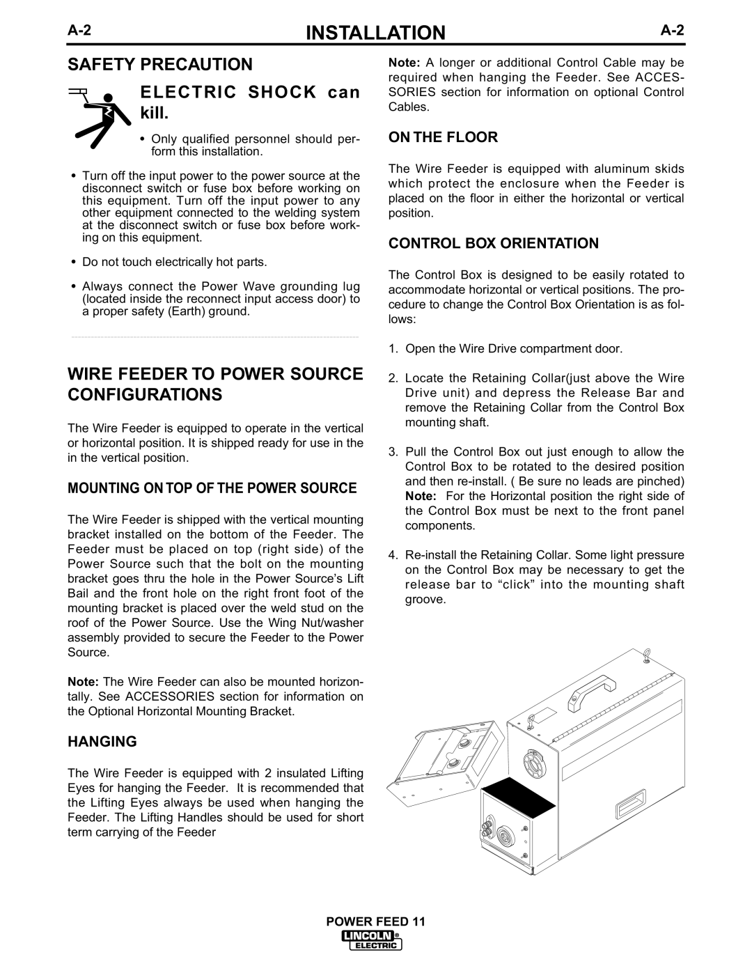
CONTROL BOX ORIENTATION
The Control Box is designed to be easily rotated to accommodate horizontal or vertical positions. The pro- cedure to change the Control Box Orientation is as fol- lows:
1.Open the Wire Drive compartment door.
2.Locate the Retaining Collar(just above the Wire Drive unit) and depress the Release Bar and remove the Retaining Collar from the Control Box mounting shaft.
3.Pull the Control Box out just enough to allow the Control Box to be rotated to the desired position and then
4.